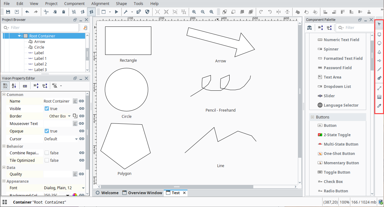
Drawing Tools
Drawing Tools Overview
Vision comes with its own set of drawing tools so you can draw your own vector graphics on a window. Using the drawing tools you can create your own shapes such as lines, rectangles, and circles. These shapes are components with their own set of properties. Shapes or graphics such as lines, rectangles, and circles can be created using the 2D drawing tools in Vision. All SVG (Scalable Vector Graphics) images are importable in Vision and are made up of these basic shapes.
Using Drawing Tools
By default, the drawing toolbar is always located on the right side, but you can drag it to anywhere on your window that you prefer. At the very top of the toolbar is a Selection ![]() tool that allows you to select various components on a window. You can use the Selection tool to change the component's size and position as well as to configure the component. Below the Selection tool are all the tools that draw graphics. Click on the tool's icon to make it the active tool, then click in the Designer and drag to place the tool in your workspace. Once you draw a graphic, and want to drag a different graphic tool on to your window, click on the Selection tool. When a drawing tool is active, a toolbar will appear in the top menubar that has specific settings and actions for that tool.
tool that allows you to select various components on a window. You can use the Selection tool to change the component's size and position as well as to configure the component. Below the Selection tool are all the tools that draw graphics. Click on the tool's icon to make it the active tool, then click in the Designer and drag to place the tool in your workspace. Once you draw a graphic, and want to drag a different graphic tool on to your window, click on the Selection tool. When a drawing tool is active, a toolbar will appear in the top menubar that has specific settings and actions for that tool.
Types of Drawing Tools
There are multiple drawing tools that each fulfill a different purpose. Some, like the selection tool simply allow you to select different components, while others like the rectangle tool allow you to create shapes. When you create a shape it has a default Fill Paint color of white. After a shape is created, you can change its Fill Paint color, Stroke color, and Stroke Style properties. All shapes can be treated as paths and be used with composite geometry functions to alter or create other shapes.
Selection Tool
The Selection ![]() tool is active by default. When this tool is active, you can select shapes and components. Selected components can be moved, resized, and rotated. For more on using the Selection tool to manipulate components and shapes, see Manipulating Components.
tool is active by default. When this tool is active, you can select shapes and components. Selected components can be moved, resized, and rotated. For more on using the Selection tool to manipulate components and shapes, see Manipulating Components.
Rectangle Tool
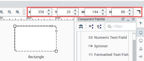
The Rectangle ![]() tool creates and edits rectangle shapes. To create a rectangle, select the tool and then click and drag inside a window to create a new rectangle. Hold down Ctrl to make it a perfect square, and the Shift key to make it grow from the center point. Once a rectangle is created, you can use the square handles to change the rectangle's height and width. This is important because it is the only way to resize a rotated rectangle and let it remain a rectangle. If you resize a non-orthogonally rotated rectangle using the Selection tool, it will skew and become a parallelogram. If you double-click on the rectangle so the tool is active, you can change the rectangle's width and height using the tool-specific handles. From the toolbar, you can also change the rectangle's location (in pixels) on the window using the X and Y axes.
tool creates and edits rectangle shapes. To create a rectangle, select the tool and then click and drag inside a window to create a new rectangle. Hold down Ctrl to make it a perfect square, and the Shift key to make it grow from the center point. Once a rectangle is created, you can use the square handles to change the rectangle's height and width. This is important because it is the only way to resize a rotated rectangle and let it remain a rectangle. If you resize a non-orthogonally rotated rectangle using the Selection tool, it will skew and become a parallelogram. If you double-click on the rectangle so the tool is active, you can change the rectangle's width and height using the tool-specific handles. From the toolbar, you can also change the rectangle's location (in pixels) on the window using the X and Y axes.
There are also small circle handles on the rectangle that allow you to alter the rectangle's corner rounding radius. Simply drag the circle down the side of the selected rectangle to make it a rounded rectangle. Hold down Ctrl to drag each rounding handle independently if you want non-symmetric corner rounding. You can use the Make Straight ![]() button in the rectangle's toolbar to return a rounded rectangle back to a standard, straight-corner rectangle.
button in the rectangle's toolbar to return a rounded rectangle back to a standard, straight-corner rectangle.
Circle Tool
The Circle ![]() tool creates and edits circles and ellipses. It is used in much the same way as the rectangle tool. While it is the active tool, you can click and drag inside a window to create a new ellipse. Hold down Ctrl to make it a perfect circle, and the Shift key to make it grow from the center point. When an ellipse is selected, use the width and height handles to alter the shape. You can also use the ellipse toolbar at the top of the Designer to change the width and the height as well as the X and Y axes.
tool creates and edits circles and ellipses. It is used in much the same way as the rectangle tool. While it is the active tool, you can click and drag inside a window to create a new ellipse. Hold down Ctrl to make it a perfect circle, and the Shift key to make it grow from the center point. When an ellipse is selected, use the width and height handles to alter the shape. You can also use the ellipse toolbar at the top of the Designer to change the width and the height as well as the X and Y axes.
Polygon Tool
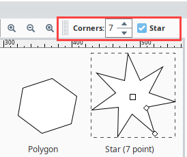
The Polygon ![]() tool is used to create polygons and stars. Use the polygon toolbar at the top that becomes visible when this tool is active to alter the settings of the shape that is created when you drag to create a polygon. This tool can be used to make any polygon with three corners (a triangle) or more. On the Polygon menu you can specify the number of corners for the polygon. Once created, you can use the center square handle to move the polygon around, and the diamond handles to alter the size and angle of the polygon. Hold down Ctrl to keep the polygon's rotation an even multiple of 15°. For a star shape, specify the number of corners (points) and select the Star check box. A second handle that is between each corner will appear on the polygon allowing you to make a star shape.
tool is used to create polygons and stars. Use the polygon toolbar at the top that becomes visible when this tool is active to alter the settings of the shape that is created when you drag to create a polygon. This tool can be used to make any polygon with three corners (a triangle) or more. On the Polygon menu you can specify the number of corners for the polygon. Once created, you can use the center square handle to move the polygon around, and the diamond handles to alter the size and angle of the polygon. Hold down Ctrl to keep the polygon's rotation an even multiple of 15°. For a star shape, specify the number of corners (points) and select the Star check box. A second handle that is between each corner will appear on the polygon allowing you to make a star shape.
Arrow Tool
The Arrow ![]() tool is used to create single or double-sided arrow shapes. When it is active, simply drag to create a new arrow. Use the checkbox on the arrow toolbar to choose a single or double-sided arrow. To alter the arrow, use the diamond handles to change the two ends of the arrow, and the circle handles to change the size of the shaft and the arrow head. When changing the arrow's direction, you may hold down Ctrl to snap the arrow to 15° increments.
tool is used to create single or double-sided arrow shapes. When it is active, simply drag to create a new arrow. Use the checkbox on the arrow toolbar to choose a single or double-sided arrow. To alter the arrow, use the diamond handles to change the two ends of the arrow, and the circle handles to change the size of the shaft and the arrow head. When changing the arrow's direction, you may hold down Ctrl to snap the arrow to 15° increments.
Pencil Tool
The Pencil ![]() tool is used to draw freehand lines and shapes. When this tool is active, you can draw directly on a window by holding down the mouse button. Release the mouse button to end the path. If you stop drawing inside the small square that is placed at the shape's origin, then you will create a closed path, otherwise, you'll create an open path (line).
tool is used to draw freehand lines and shapes. When this tool is active, you can draw directly on a window by holding down the mouse button. Release the mouse button to end the path. If you stop drawing inside the small square that is placed at the shape's origin, then you will create a closed path, otherwise, you'll create an open path (line).
On the pencil toolbar, there are options for simplification and smoothing, as well as a toggle between creating straight line segments or curved line segments. The simplification parameter is a size in pixels that will be used to decrease the number of points used when creating the line. Points will be in general as far apart as this setting. If you find the line isn't accurate enough, decrease this setting. If you choose to create curved segments, then the segments between points will be Bézier curves instead of straight lines. The smoothing function controls how curvy these segments are allowed to get.
Line Tool
The Line ![]() tool can be used to draw lines, arbitrary polygons, or curved paths. Unlike all of the other tools, you don't drag to create new paths with the line tool. Instead, you click for each vertex you'd like to add to your path.
tool can be used to draw lines, arbitrary polygons, or curved paths. Unlike all of the other tools, you don't drag to create new paths with the line tool. Instead, you click for each vertex you'd like to add to your path.
To draw a straight line, simply click once where you want the line to start, and double-click where you want the line to end. To make a multi-vertex path, click for each vertex and then double-click, press enter, or make a vertex inside the origin box to end the path.
As you draw the line, "locked-in" sections are drawn in green and the next segment is drawn in red. Hold down Ctrl at any time to snap the next segment to 15° increments.
On the line toolbar, you can choose between three different type of line settings:
- straight-line segments
- perpendicular-line segments
- curve-line segments
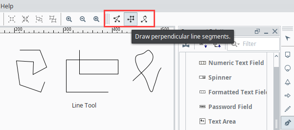
Perpendicular-line segment is just like a straight-line segment except that each segment is restricted to either horizontal or vertical.
The curve-line segment will create a Bézier curve path by attempting to draw a smooth curve between the previous two vertices and the new vertex.
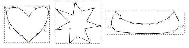
Path Tool
All shapes and paths can be edited directly by using the Path ![]() tool. This tool lets you directly modify the nodes in the path, adding new nodes, removing nodes, and toggling segments between straight or curved. For more information, see Shape Geometry.
tool. This tool lets you directly modify the nodes in the path, adding new nodes, removing nodes, and toggling segments between straight or curved. For more information, see Shape Geometry.
Gradient Tool
The Gradient ![]() tool is used to affect the orientation and length of any gradient paints. They work hand-in-hand with the Fill Paint property. Gradients smoothly blend any number of colors that can be positioned along a straight line or form an ellipse across the shape. A Linear gradient uses a horizontal line drawn across the width of the shape by default. By switching to the gradient tool, the horizontal line can be changed to move in any direction by dragging the handles. The Radial gradient uses a 45° angle drawn over the shape which starts at the center and moves out. Just like the Linear gradient, the Radial gradient can also be changed by dragging the handles around.
tool is used to affect the orientation and length of any gradient paints. They work hand-in-hand with the Fill Paint property. Gradients smoothly blend any number of colors that can be positioned along a straight line or form an ellipse across the shape. A Linear gradient uses a horizontal line drawn across the width of the shape by default. By switching to the gradient tool, the horizontal line can be changed to move in any direction by dragging the handles. The Radial gradient uses a 45° angle drawn over the shape which starts at the center and moves out. Just like the Linear gradient, the Radial gradient can also be changed by dragging the handles around.

Eyedropper Tool
With the Eyedropper ![]() tool you can set a selected shape(s) and/or component(s) foreground/background or stroke/fill colors by pulling the colors from somewhere else in the window. Select the component you want to change, and then activate the eyedropper tool. When this tool is active, left-click to set the selection's fill or background color, and right-click to set the selection's stroke or foreground color.
tool you can set a selected shape(s) and/or component(s) foreground/background or stroke/fill colors by pulling the colors from somewhere else in the window. Select the component you want to change, and then activate the eyedropper tool. When this tool is active, left-click to set the selection's fill or background color, and right-click to set the selection's stroke or foreground color.
Remember to turn off the Eyedropper tool when you're finished by clicking the Selection tool, otherwise, you will continue to change colors on your component each time you do a mouse click. This tool works on most components as well as shapes. For example, right clicking will set the font color on a Button component, or left-clicking will set the background color.
Shape Size, Position, and Angle
Shapes are different from other components in that they have properties that determine their size and position that can easily be bound. These properties are called X, Y, Height, and Width. The values of these properties are always relative to the shape's parent container's width and height, even in a running Client where that container may be a wildly different size due to the layout mechanism.
For example, let's say that you have a shape that is located at x=100, y=100, and was 125 by 125 inside a container that is 500 by 500. If you want to animate that shape so that it moves back and forth across the screen, you'd set up a binding so that X changed from 0 to 375. (You want X to max out at 375 so that the right-edge of the 125px wide shape aligns with the right edge of the 500px container). Now, at runtime, that container might be 1000 by 1000 on a user's large monitor. By binding X to go between 0 and 375, the true X value of your shape (whose width will now be 250px due to the relative layout system), will correctly move between 0 and 1750, giving you the same effect that you planned for in the Designer.
Another ability unique to shapes is the ability to be rotated. Simply click on a selected shape and the resize controls become rotate controls. There's even an Angle property that can be edited directly or bound to something dynamic like a Tag.
Use caution when binding the rotation. When you change a shape's rotation, its position also changes. The position of any shape is the top-leftmost corner of the rectangle that completely encloses the shape. Because of this effect, if you wish to both dynamically rotate and move a component, special care must be taken since rotation alters the position.
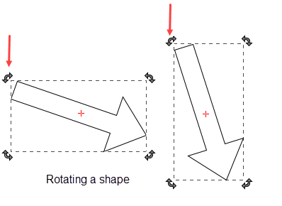
If you want to both dynamically rotate and move a component, special care must be taken since rotation alters the position. You don't want your position binding and the rotation binding fighting over the position of the component. The way to both rotate and move a shape is as follows:
- Bind the rotation on your shape as you wish.
- Create a shape (for example, a rectangle) that completely encloses (in other words, it's bigger than) your shape at any rotation angle.
- Set that rectangle's visible property to false.
- Select your shape and the rectangle and group them.
- Bind the position on the resulting group.
Now the rotation and position of a shape are animated.