Perspective Pipes
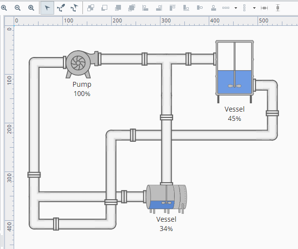
Pipes are created by a dedicated drawing tool on the toolbar, as opposed to being dragged onto a container like other components. Pipes are effectively drawn on the bottom of the z-order in a coordinate container, hence any components added into the container will always be placed above the pipes.
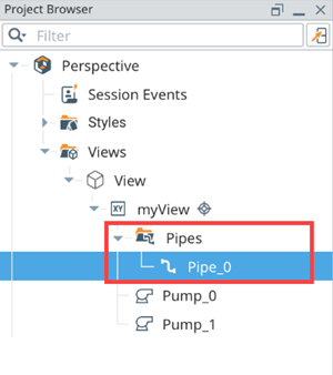
Each pipe consists of an origin, its connections, connections of connections, and so on. Each pipe is listed as a separate entry in the Project Browser, under "Pipes".
Terminology

Pipe
An object containing all the pipe connections and pipe segments. In addition, a Pipe contains a name, appearance, and appearance specific props.
Pipe Connection
An XY coordinate within the pipe. Visualized as a circle.
Origin
The first Pipe Connection within a pipe. Note that origins differ visually from other Pipe Connections, in that they contain a dot at their center.
Pipe Segment
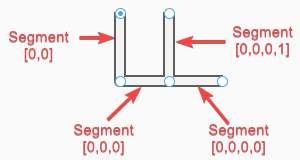
The segment formed by a Pipe Connection, and one of its immediate child connections. A segment is a visual representation of relationship between other connections. Each connection has an array of connection indices (starting at 0), and segments can be represented as a series of indices. For example, [0,1,0] would represent the first pipe, second connection, then first sub connection.
Consider the simple pipe below of three connections and two pipe segments. The top of Segment [0,0] is the origin and the bottom of Segment [0,0] is the pipe connection where Segment [0,0,0] begins, turning the pipe flow from a vertical to horizontal direction. The end of Segment [0,0,0] is the final connection.

We can add two new connections, which could look like the following diagram. Because of the connection locations, Segment [0,0,0,0] follows the existing naming structure, but Segment [0,0,0,1] is given the number 1 since it was added later and is the second child.
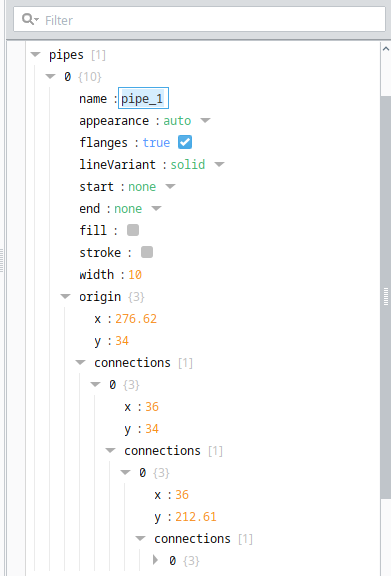
Note that segment indices are represented in the Project Browser.
[
  {
    "name": "pipe",
    "appearance": "auto",
    "flanges": true,
    "lineVariant": "solid",
    "start": "none",
    "end": "none",
    "fill": "",
    "stroke": "",
    "width": 10,
    "origin": {
      "x": 258,
      "y": 168,
      "connections": [
        {
          "x": 258,
          "y": 236,
          "connections": [
            {
              "x": 307,
              "y": 236,
              "connections": [
                {
                  "x": 360,
                  "y": 236
                },
                {
                  "x": 307,
                  "y": 168
                }
              ]
            }
          ]
        }
      ]
    }
  }
]
Creating Pipes
Click on the Pipe Drawing Tool ![]() toward the top of the Designer. While active, clicking anywhere inside a coordinate container will create a new Pipe with an origin at the mouse location.
toward the top of the Designer. While active, clicking anywhere inside a coordinate container will create a new Pipe with an origin at the mouse location.
Pipes can only be drawn in a Coordinate Container. The Pipe Draw Tool and Pipe Move Tool will be disabled while other types of containers are selected.
By default, a Coordinate Container's aspectRatio property does not have a value. As such, setting your container's aspectRatio to a value like 1:1 when creating Pipes is recommended. This helps Pipes remain anchored to components if the components change size in proportion with the container.

All connections, including the origin, can be repositioned by clicking and dragging.
New connections can be drawn by dragging the arrows around the connection. Letting go will create a new connection. By default, all segments are drawn orthogonally. Holding the Alt/Option key will allow the segment to be drawn in fixed angles at 15 degree increments. Alternatively, holding Shift while dragging allows the segment to be placed freely without snapping.

New connections can be added to existing segments. Doing so allows the segment to split off into a new segment.
To delete a segment, click on a connection in the segment and press the Delete key, or by right-clicking and selecting "Delete".
Existing connections can be moved by dragging. All attached segments will move with the origin.
If Shift is held while repositioning a connection, then connecting segments will bend.
Moving Pipe Sets
The Pipe Move Tool ![]() can be used to move an entire set of pipes, as well as resize the set.
can be used to move an entire set of pipes, as well as resize the set.
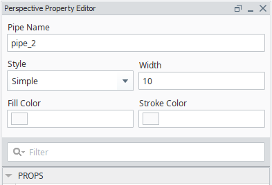
Pipe Appearance Editor
While either the Pipe Draw Tool or Pipe Move Tool are selected, the top of the property editor will display some additional fields that can be used to modify the appearance of the selected set of pipes. Additional fields are displayed depending on the selected Appearance of the pipe.
When multiple pipes are selected, only shared fields are displayed. For example, one pipe with an appearance of P&ID and another using simple appearance are selected, only the Appearance and Width properties will be shown since those are the only fields available to both appearances.

In addition, a coordinate container that has one or more sets of pipes will display a pipes property in the Property Editor. Each origin is represented as an element in the pipes array. Each origin has X and Y coordinates, and an array of connections, which lead to other origins.
Pipe Properties
| Property | Description |
|---|---|
| Pipe Name | The name of the selected set of pipes, as they appear in the Project Browser. |
| Appearance | Changes the look of the pipes. Note that different appearances have additional properties. In addition to the appearance options, there is an auto value will will cause the set to use the appearance specified under session.props.pipes.autoAppearance. |
| Width | Determines the width of pipes in pixels within a single set. |
| Fill Color | The fill color to use when appearance is set to either Simple or Mimic. This setting is ignored when appearance is set to P&ID. |
| Stroke Color | The stoke color to use when appearance is set to either Simple or Mimic. This setting is ignored when appearance is set to P&ID. |
| Display flanges on pipe (Mimic Appearance Only) | Determines if the pipe set should show flanges. |
| Line Variation (P&ID Appearance Only) | Allows a unique variation to be applied to the set.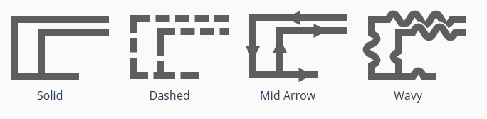 |
| Line Color (P&ID Appearance Only) | The color to use for the pipe set. |
| Start (P&ID Appearance Only) | Determines what the start of a pipe set look like. Applies to the starting origin of a set. |
| End (P&ID Appearance Only) | Determines what the end of a pipe set look like. Applies to all origins that don't lead into another origin. |
| Visible | New in 8.1.13 Determines whether the pipe set is visible or not. Default setting is True. |
Combining Pipes
Dragging a pipe to another will combine the pipes. Combining pipes will cause the pipes to share the same appearance. However this combination can be overridden by pressing the Undo button (or by pressing Ctrl-Z/Command-Z) once. This allows different pipes to overlap without actually combining.
Additionally, a connection can be dragged onto it's immediate sibling or parent, which effectively removes the dragged connection.
Component Anchors
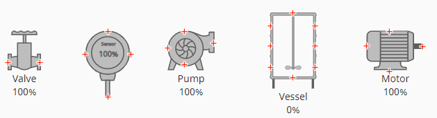
While using the Pipe Drawing Tool, other components in the container will display anchor points.

Symbol type components have custom anchors, positioned at appropriate locations.
Dragging a segment near the anchor will cause the segment to snap to the anchor (unless the Shift key is currently being held). This can be useful when leading segments into different components. Note that anchors are only used to guide the segment in the designer. The pipes are not "connected" to the component, so moving the component later will not cause the pipe segment to move.