Modbus Addressing
Manually Addressing a Modbus Device
Modbus doesn't support tag browsing, this means you cannot view the Tags in the Connected Devices window in the Designer or from the OPC Connections > Quick Client in the Config section of the Gateway.
There are two ways you can create tags so that you can browse them:
-
By manually specifying each address
- This is done from the Designer by entering Modbus Specific Addresses into the OPC Item Path of an OPC Tag. See below for detailed information.
-
By specifying the address mapping
- This is done from the Gateway, see the Modbus Address Mapping section.
To manually specify each address
You can enter Modbus specific addresses into the OPC Item Path of an OPC Tag by using the following designators along with the Modbus address:
-
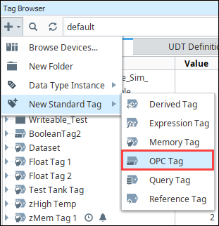
In the Tag Browser, click the Add (
 ) icon.
 -
Select New Standard Tag then OPC Tag.
-
In the Tag Editor window, as an example, you can set the following values:
- Name: Temp
- Data Type: Integer
- OPC Server: Choose Ignition OPC UA Server from the dropdown.
- OPC Item Path: [Modbus]HR1. The Modbus device name goes in the square brackets. Next, you give the address to the PLC which in this case is the HR designator plus 1 as the Modbus address. The Modbus Specific Addressing section below, explains how you can construct these addresses.
-
Click OK. Now you can see the Temp tag in the Tag Browser.
Modbus Specific Addressing
Per the Modbus protocol specification, the following four basic types of addresses can be read from a device:
- Holding Registers (read/write 16 bit words)
- Input Registers ( read only 16 bit words)
- Coils (read/write bits)
- Discrete Inputs (read only bits associated with device input points)
Manually Create an Address for a Single Tag
To manually enter Modbus Specific Addresses into the OPC Item Path of the Tag Editor window, use one of the following designators plus the Modbus address:
Other OPC servers represent each type by starting the OPC address with a number, for example, 4 for holding registers.
| Designator | Description |
|---|---|
| HR | for 16 bit signed Holding Register (HR1, equivalent to 40001 in other applications) |
| IR | for 16 bit signed Input Register (IR1, equivalent to 30001) |
| C | for Coil (C1, equivalent to 00001) |
| DI | for Discrete Input (DI1, equivalent to 10001) |
An example of using these designators with the Modbus address is to enter HR1 in the OPC Item Path of an OPC Tag in the Tag Editor window, which is the HR designator plus the Modbus address 1.
Because some devices that support Modbus protocol store data in BCD format, there are two additional designators. These designators convert the data from BCD format to decimal when reading data from the device and convert data from decimal to BCD when writing to the device.
| Designator | Description |
|---|---|
| HRBCD | for Holding Register with BCD conversion. |
| HRBCD_32 | for 2 consecutive Holding Registers with BCD conversion. |
| IRBCD | for Input Register with BCD conversion. |
| IRBCD_32 | for 2 consecutive Input Registers with BCD conversion. |
To accommodate other data encoding commonly used by Modbus supported devices, the following designators are available for Modbus specific addressing:
Float/Double
| Description | Holding Register Designator | Input Register Designator |
|---|---|---|
| 2 consecutive Registers with Float conversion. | HRF | IRF |
| 4 consecutive Registers with Double conversion. | HRD | IRD |
Integer
| Description | Holding Register Designator | Input Register Designator |
|---|---|---|
| Holding Registers with 16 bit unsigned integer conversion. | HRUS | IRUS |
| 2 consecutive Registers with 32 bit integer conversion. | HRI | IRI |
| 2 consecutive Registers with 32 bit unsigned integer conversion. | HRUI | IRUI |
| 4 consecutive Registers with 64 bit integer conversion. | HRI_64 | IRI_64 |
| 4 consecutive Registers with 64 bit unsigned integer conversion. | HRUI_64 | IRUI_64 |
To read or write string values from/to a Modbus device, the following designation is available for Modbus specific addressing:
| Designator | Description |
|---|---|
| HRS | read or write consecutive Holding Registers as a string value. |
There are two characters for each word and the order of which character comes first is controlled by the Reverse String Byte Order device setting as described in the Connecting to Modbus Device section. Because two characters are stored in a word, the string length must be an even number of characters.
HRS FORMAT: HRS<Modbus address>:<length>
| Examples | Description |
|---|---|
[DL240]HR1024 | Read 16bit integer value from Holding Register 1024. |
[DL240]HRBCD1024 | Read BCD value from Holding Register 1024. |
[DL240]IR512 | Read 16bit integer value from Input Register 512. |
[DL240]C3072 | Read bit value from Coil 3072. |
[DL240]IR0 | Read 16bit integer value from Input Register 0. |
[DL240]HRS1024:20 | Read 20 character string value starting at Holding Register 1024. |
You can also specify the Modbus unit ID by pre-pending it to the Modbus address. For example, to access Modbus unit ID 3 and read HR1024, the full OPC path is as follows:
[DL240]3.HR1024
Bit-level addressing
For bit-level addressing, you just append a period and the bit number you want to read and write to a bit. Your Modbus device must support the Mask Write command (your device documentation should specify if it does).
To read or write to a specific bit within a holding register, simply append the location of the bit as demonstrated in these examples:
- [DL240]HR1024.0 will read and write to the first bit of the holding register.
- [DL240]HR1024.10 will read and write to the 11th bit of the holding register.