Connecting to Modbus Device
-
Go to the Config section of the Gateway Webpage.
-
Scroll down and select OPC UA > Device Connections.

-
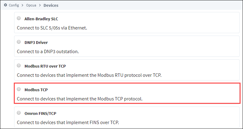
On the Devices page, find the orange arrow and click on Create new Device. There a few options to choose from:
-
Modbus RTU over TCP: Which connects to devices that implement the Modbus RTU protocol over TCP.
-
Modbus TCP: Which connects to devices that implement the Modbus TCP protocol.
-
Modbus RTU (only available if the Serial Support Gateway module is installed): Connects to a device via Modbus RTU over serial.
Changed in 8.1.20Starting in version 8.1.20, the Modbus RTU driver no longer requires the Serial Support Gateway module to function.
-
-
In this example we'll select Modbus TCP, and click Next.
-
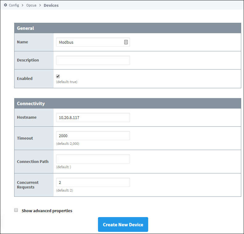
On the New Device page, leave all the default values and type in the following fields:
- Name: Modbus
- Hostname: Type the IP address. For example, 10.20.8.117.
-
You can check the box for Show advanced properties to see the additional settings, or you can keep all the defaults.
-
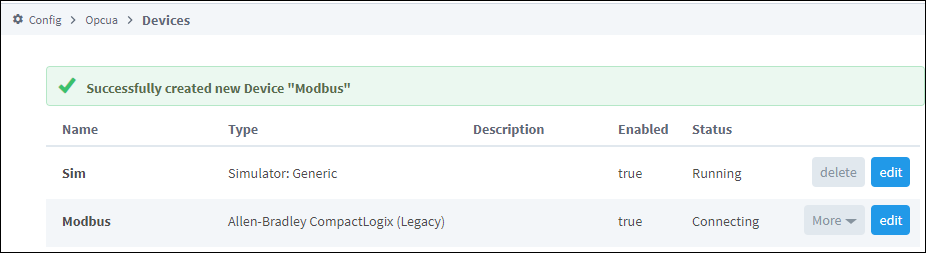
Click Create New Device. The Devices page is displayed showing the Modbus device is successfully created and added to Ignition. The Status will show as Disconnected and then Connected.
Unlike other PLCs, Modbus devices do not support browsing, therefore you can not browse the Tags by going to the OPC Connections > Quick Client in the Configure section of the Gateway. To see and browse the Tags, you need to create the Tags as described in the Modbus Addressing section.
Modbus Drivers using Ethernet
The generic Modbus driver allows the Ignition OPC-UA server to communicate with any device that supports Modbus TCP protocol. The Modbus driver can connect directly to devices that support Ethernet communications. It can also connect to Modbus devices through a Gateway.
It is important to only add one Modbus device in the Ignition Device List per IP address. When communicating to multiple Modbus devices through a Gateway each with a unique unit ID, either include the unit ID in the Modbus specific address or set it in the address mapping for the device.
Supported Functions Codes
The Modbus driver supports the functions codes listed below. In some cases, a device may not allow certain function codes. To remedy this, advanced properties on the device connection can restrict or force specific functions codes. See the Device Connection Settings section on this page for more details.
| Function Name | Code | Hex |
|---|---|---|
| Read Discrete Inputs | 02 | 0x02 |
| Read Coils | 01 | 0x01 |
| Write Single Coil | 05 | 0x05 |
| Write Multiple Coils | 15 | 0x0F |
| Read Input Register | 04 | 0x04 |
| Read Holding Register | 03 | 0x03 |
| Write Single Register | 06 | 0x06 |
| Write Multiple registers | 16 | 0x10 |
| Mask Write | 22 | 0x16 |
Device Connection Settings
General
| Name | Description |
|---|---|
| Name | The user-defined name for this Device. The name chosen will show up in OPC Item Paths and under OPC-UA Server > Devices of the Configure page of the Gateway. The Device Name must be alphanumeric. |
| Description | The user-defined description for the device. This is only used as a note to differentiate between devices. |
| Enable Device | Only devices that are enabled appear in Connections > Devices of the Status page of the Gateway, and thus have their tags available for use. |
Connectivity (Modbus RTU over TCP and Modbus TCP connections)
| Name | Description |
|---|---|
| Hostname | Is the IP Address of the Modbus device. |
| Port | Is the port to use when connecting to a Modbus device. The Modbus TCP port specified in the Modbus specification is 502, but it can be changed to a different port. |
| Local Address | New in 8.1.8 The local address to connect from when establishing a TCP connection. If left blank, then the driver will simply pick an available address. |
| Communication Timeout | Is the amount of time in milliseconds to wait for a response before treating it as a failure, after sending a request to the Modbus device. Note: When working with a Modbus RTU over TCP connection, each "device" would be an individual Modbus device on the Modbus network. |
Connectivity (Modbus RTU connections)
| Name | Description |
|---|---|
| Serial Port | The name of the Serial Port (i.e COM1). |
| Bit Rate | The bit rate for the connection. |
| Data Bits | Data bits for the connection. |
| Parity | Parity configuration for the connection. |
| Stop Bits | Determines the stop bits for the connection. |
| Handshake | Determines the handshake for the connection. |
| Communication Timeout | Determines the maximum amount of time the connection will wait for a response. |
| RS-485 Mode | New in 8.1.25 Enables RS-485 mode when checked for a device using RS-485 instead of RS-232. RS-232 mode is the default mode. |
Advanced
| Name | Description |
|---|---|
| Concurrent Requests | New in 8.1.0 The number of requests that Ignition will try to send to the device at the same time. Increasing this number can sometimes help with your request throughput, however increasing this too much can overwhelm the device and negatively impact communications with the device. |
| Max Holding Registers per Request | The maximum number of Holding Registers the device can handle. Because some Modbus devices cannot handle the default of requesting 125 Holding Registers in one request, to accommodate this limitation you can change this setting. |
| Max Input Registers per Request | The maximum number of Input Registers the device can handle. Because some Modbus devices cannot handle the default of requesting 125 Input Registers in one request, to accommodate this limitation you can change this setting. |
| Max Coils per Request | The maximum number of Coils the device can handle. Because some Modbus devices cannot handle the default of requesting 2000 Coils in one request, to accommodate this limitation you can change this setting. |
| Max Discrete Inputs per Request | The maximum number of Discrete Inputs the device can handle. Because some Modbus devices cannot handle the default of requesting 2000 Discrete Inputs in one request, to accommodate this limitation you can change this setting. |
| Reverse Word Order | When reading and writing 32bit values from/to a Modbus device, the high word comes before the low word. By checking this option, the low word comes before the high word. The Modbus specification does not include a section for reading and writing 32bit values and as a result device manufacturers have implemented both methods. |
| Zero-based Addressing | When this option is checked, the address range for each area starts at 0. If unchecked, the range starts at 1. The Modbus specification states that Modbus addresses are to be zero based. Meaning Modbus addresses start at 0 instead of 1. To read a value from Modbus address 1024, 1023 is sent to the device. When connecting to devices that do not adhere to zero based addressing, make sure this option is not selected. |
| Span Gaps | When this option is checked, it spans address gaps when optimizing requests, reducing the number of requests but increasing the amount of data requested at once. If unchecked, it does not span the address gaps. |
| Allow Write Multiple Registers Request | Enable or disable Modbus function code 0x10, Write Multiple Registers. Some devices may not support this function code. Caution: Disabling this option will break the ability to write 32-bit and String values correctly to registers. |
| Force Multiple Register Writes | Force the use of Modbus function code 0x10, Write Multiple Registers, on write requests. |
| Allow Write Multiple Coils Request | Enable or disable Modbus function code 0x0F, Write Multiple Coils. Some devices may not support this function code. |
| Allow Read Multiple Registers Request | If disabled all registers will be read in individual read requests. Disable with caution. |
| Allow Read Multiple Coils | If disabled all coils will be read in individual read requests. Disable with caution. |
| Allow Read Multiple Discrete Inputs | If disabled all discrete inputs will be read in individual read requests. Disable with caution. Note: Function code 0x02 is always used to read Discrete Inputs, regardless what this property is set to. |
| Reconnect After Consecutive Tries | Force a reconnect after 3 consecutive timeouts. Default is true. |
| Max Retry Count | Maximum number of times to retry a read request after receiving a response containing an allowable Exception Code (GatewayPathUnavailable, GatewayTargetDeviceFailToRespond, SlaveDeviceBusy, or SlaveDeviceFailure). Default is 1. |
String Handling
| Name | Description |
|---|---|
| Reverse String Byte Order | When reading and writing string values from/to a Modbus device, the low byte comes before the high byte. By checking this option the high byte comes before the low byte. If reading a string value from a device should read ABCD but BADC appears in Ignition, then check this option. |
| Right Justify Strings | Strings stored in a Modbus device may contain leading spaces or trailing spaces. This can produce unwanted results so that Modbus driver removes spaces or zeros when reading string values. By default, left justify string handling is used when reading and writing strings. When you check this option, right justify string handling is used. |
| Read Raw Strings | Whether or not to read the entire length of a string, ignoring any null bytes encountered. |