Siemens
The Siemens drivers in Ignition support basic connections to S7 devices. Ignition connects to these PLCs via TCP/IP using the S7 protocol. Similar to Modbus and some Allen Bradley connections, the Siemens S7 devices do not support tag browsing. You can create S7 tags manually in Ignition, or use Ignition's tag import/export to create all of your tags quickly in Excel or another spreadsheet program. Currently, Ignition has drivers for the following Siemens PLCs:
- S7-300
- S7-400
- S7-1200
- S7-1500
Some S7-1200 and S7-1500 devices have an onboard OPC UA server that can be enabled to connect over the OPC UA server instead of using the Siemens driver. OPC UA allows you to browse tags, while the driver requires you to address each tag manually.
Considerations for 1200 and 1500 Devices
The requirements listed below apply when connecting to either the S7-1200 and S7-1500 drivers:
-
Only global DBs can be accessed.
-
Reading and writing is not supported for timer (TM) and counter (CT) areas.
-
The Optimized block access attribute option must be turned off.
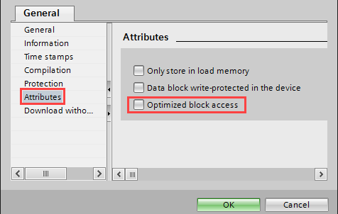
-
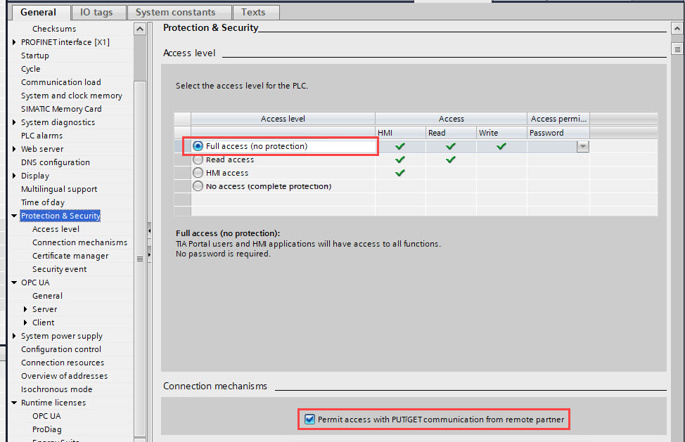
When configuring the Protection & Security settings, make sure the Full access (no protection) and Permit access with PUT/GET communication options are selected.
This change may require the hardware configuration to be recompiled and downloaded. Additionally, disabling "optimized access" for the data block(s) you are attempting to read may also improve the reliability of tag reads.
Connecting to a Siemens Device
- Go to the Config section of the Gateway Webpage.
- Scroll down and select OPC UA > Device Connections.
- On the Devices page, click on Create new Device.
- On the Add Device Step 1: Choose Type page, select Siemens S7-1200, and click Next.
- There are four modules to choose from:
- Siemens S7-1500: Connects to Siemens S7-1500 PLCs over Ethernet.
- Siemens S7-1200: Connects to Siemens S7-1200 PLCs over Ethernet.
- Siemens S7-300: Connects to Siemens S7-300 PLCs over Ethernet.
- Siemens S7-400: Connects to siemens S7-400 PLCs over Ethernet.
- On the New Device page, leave all the default values and type in the following fields:
- Name: S71200
- Hostname: type the IP address, for example 10.20.4.71.
- You can check the box for Show advanced properties? to see the additional settings, but you can keep all the defaults.
- Click Create New Device. The Devices page is displayed showing the Siemens device is successfully created and added to Ignition. The Status will show as Disconnected and then Connected.
Siemens devices do not support browsing, therefore you can not browse the tags by going to the OPC Connections > Quick Client in the Configure section of the Gateway. To see and browse the tags, you need to create the tags manually as described in the Configuring Siemens Addressing section.
Configuring Siemens Addressing
The S7 protocol does not support tag browsing. Therefore, you must configure all tags in the Designer. This can be done either manually, as needed, or by importing bulk using the tags CSV import functionality.
Manually Specify Each Address
-
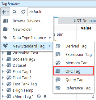
From the Designer, in the Tag Browser, click the Add (
 ) icon.
 -
Select New Standard Tag, then OPC Tag.
-
In the Tag Editor window, as an example, you can set the following values:
- Name: Tag
- Data Type: Int4
- OPC Server: choose Ignition OPC-UA Server with the edit button on the right.
- OPC Item Path: [S71200]IW0, the S71200 device name goes in the square brackets then you give the address to PLC which in this example is IW0 (Word at Offset 0 in the Inputs area). The Address Syntax section explains how you can construct these addresses.
-
Click OK. Now you can see the Temp tag in the Tag Browser.
Address Syntax
You need a device name plus a tag address to create a tag. The device name is a known, but the tag address needs to be configured. Once you have both the device name and tag address you enter them in the in the OPC Item Path field of the Tag Editor window using the [device_name]address format, where device_name is the name of the device and address is the configured tag address, which is described here.
Tag addresses are made up of three different components: Area, Data Type, and Offset.
Area Syntax
| Area | Syntax |
|---|---|
| DataBlocks | DBn |
| Inputs | I |
| Outputs | Q |
| Flags | M |
| Timers | T |
| Counters | C |
Data Type Syntax
| Data Type | Syntax | Signedness |
|---|---|---|
| Bit | X | N/A |
| Byte | B | Unsigned |
| Char | C | Signed |
| Word | W | Unsigned |
| Int | I | Signed |
| DWord | D | Unsigned |
| DInt | DI | Signed |
| Real | REAL | Signed |
| String | STRING or STRING.LEN | N/A |
| Date_And_Time | New in 8.1.29 DT Note: Due to limitations on Siemens devices, this data type is only supported on the following devices:
| N/A |
| LInt | New in 8.1.29 LI Note: Due to limitations on Siemens devices, this data type is only supported on the following device:
| Signed |
| LReal | New in 8.1.29 LREAL Note: Due to limitations on Siemens devices, this data type is only supported on the following devices:
| Signed |
The Siemens driver does not support Ignition tag's DateTime type. In these cases it is recommended to extract each byte in the Siemens DATE_AND_TIME value item, storing each into a separate Ignition tag. Then use an expression tag to combine each byte into a human readable datetime.
// The following assumes each byte of the DATE_AND_TIME value is under a tag named like "BASIC_DATA_AND_TIME", and that each tag is a String type.

"20" + //First part of the year, assuming in 21st century
toHex({[.]BASIC_DATE_AND_TIME[0]}) + “-” +                  //Second part of the year, reading from an Ignition tag.
numberFormat(toHex({[.]BASIC_DATE_AND_TIME[1]}), “00”) + “-” + //Month
numberFormat(toHex({[.]BASIC_DATE_AND_TIME[2]}), “00”) + “-” + //Day
numberFormat(toHex({[.]BASIC_DATE_AND_TIME[3]}), “00”) + “:” + //Hours
numberFormat(toHex({[.]BASIC_DATE_AND_TIME[4]}), “00”) + “:” + //Minutes
numberFormat(toHex({[.]BASIC_DATE_AND_TIME[5]}), “00”) + “:” + //Seconds
numberFormat(fromBinary(left(numberFormat(toBinary({[.]BASIC_DATE_AND_TIME[6]} + {[.]BASIC_DATE_AND_TIME[7]}), “0000000000000000”), 12)), “000”) + " " + //Milliseconds, it includes the first 4 bits of byte 7
case( //Day of the week, last 4 bits of byte 7
right(numberFormat(toBinary({[.]BASIC_DATE_AND_TIME[7]}), “00000000”), 4),
“0000”, “Sunday”,
“0001”, “Monday”,
“0010”, “Tueday”,
“0011”, “Wednesday”,
“0100”, “Thursday”,
“0101”, “Friday”,
“0111”, “Saturday”,
“Error - No Day Found”)
Area + Data Type + Offset Examples
To form an address, you combine syntax for the desired Area and Data Type with an Offset into that area.
| Address | Description |
|---|---|
IB0 | Byte at Offset 0 in the Inputs area. |
IW0 | Word at Offset 0 in the Inputs area. |
DB500,DI8 | DInt at Offset 8 in DataBlock 500. |
ISTRING24.50 | A String of length 50 starting at offset 24 in the Inputs area. |
IX20.3 | Bit 3 of the Byte at Offset 20 in the Inputs area. |
T0 | Timer at offset 0 (No DataType is specified for Timers). |
C0 | Counter at offset 0 (No DataType is specified for Counters). |
Offsets
It is important to note that offsets are absolute. IW0 and IW1 share a byte. To get two consecutive, non-overlapping words you need to address IW0 and IW2.
Bits
Bits are addressed by using the Bit data type (X) and appending .bit to the end, where bit is in the range [0-7]. When addressing a bit at a given offset, that offset is always treated as a byte.
Strings
Strings are assumed to be in the S7 string format and have a max length of 210.
Timers
Timers are scaled up to a DWord and converted from S5 time format so they can represent the time in milliseconds without requiring any multipliers. When you write to a timer it is automatically converted from milliseconds into S5 time format for you. A data type is not specified when accessing timers.
Counters
Counters in the PLC are stored in BCD. The driver automatically converts to/from BCD for you and exposes any counter Tags as UInt16 values. A data type is not specified when accessing counters.
Device Settings
General
| Setting | Description |
|---|---|
| Name | The name of the Device Connection. |
| Description | A description for the Device Connection. The description will appear on the Devices page on the Gateway. |
| Enabled | Whether or not the connection is active. Disabling this setting terminates communication with the device. |
Connectivity
| Setting | Description |
|---|---|
| Hostname | The hostname or IP address of the device. |
| Local Address | New in 8.1.8 The local address to connect from when establishing a TCP connection. If left blank, then the driver will simply pick an available address. |
| Timeout | The request timeout, specified in milliseconds. The default is 2,000. |
Advanced
| Setting | Description |
|---|---|
| Port | The port to use when connecting to the device. The default is 102. |
| PDU Size | Number of bytes to fit into PDU block of a single packet. Increasing this number can improve request throughput only if the processor supports a higher PDU Size. Varies from 240 and up to 960 depending on the device. The default is 240. |
| Rack Number | The number of the rack that the device is positioned in. The default is 0. |
| CPU Slot Number | The slot number assigned to the CPU. The default is 2. |
| Reconnect After Consecutive Timeouts | After several consecutive timeouts, the Device Connection will attempt to reconnect to the Device. Default is true. |