Omron FINS Driver
Ignition supports Omron FINS devices. This driver supports both UDP and TCP transport protocols.
Connect Ignition to an Omron FINS Device via TCP
-
Go to the Config section of the Gateway Webpage.
-
Scroll down and select OPC UA > Device Connections.

-
On the Devices page, click on Create new Device.
-
Select Omron FINS/TCP, and click Next.
-
Fill in the following fields:
- Name: FINS TCP
- Hostname: Enter the IP address, for example 74.125.224.72
Leave the default values in the remaining fields.
-
Click Create New Device.
The Devices page is displayed showing the FINS TCP device is successfully created and added to Ignition.
Connect Ignition to an Omron FINS Device via UDP
- Go to the Config section of the Gateway Webpage.
- Scroll down and select OPC UA > Device Connections.
- On the Devices page, click on Create new Device.
- Select Omron FINS/UDP, and click Next.
- Fill in the following fields:
- Name: FINS UDP
- Bind Address: Enter the IP address of your Gateway, for example 74.125.225.10
- Remote Address: Enter the IP address of your Omron FINS device, for example 74.125.224.72
- Under FINS Settings set the following:
- FINS Source Node: The last octet of your IP address, for example 10 using the bind address above.
- FINS Destination Network: The address number of your FINS device typically configured in the routing table for your device. The valid range is 0-128.
- FINS Destination Node: The node number of your FINS device. This is typically the last octet of the IP address of the device, for example 72 in the example above.
- Fins Destination Unit: The unit number of your FINS device.
- Click Create New Device.
The Devices page is displayed showing the FINS UDP device is successfully created and added to Ignition.
Device Settings
General
| Property | Description |
|---|---|
| Name | Device Name |
| Description | Device description |
| Enabled | Default is set to true. |
Connectivity
| Property | Description | TCP or UDP |
|---|---|---|
| Hostname | The hostname or IP Address of the device. | TCP Only |
| Port | The port your Omron device is listening on. The default is 9600. | TCP Only |
| Local Address | Address of network adapter to connect from. | TCP Only |
| Bind Address | The hostname or IP address of the Gateway | UDP Only |
| Bind Port | The port you wish to create a UDP connection on for the Gateway. The default is 9600. | UDP Only |
| Remote Address | The hostname or IP address of the device. | UDP Only |
| Remote Port | The port your Omron device is listening on. The default is 9600. | UDP Only |
| Timeout | The request timeout, specified in milliseconds. The default is 2,000. | UDP & TCP |
FINS Settings
| Property | Description | Valid Value |
|---|---|---|
| FINS Source Network | The address number of the source network (the Ignition Gateway). | Valid value is an integer between 0 and 127. The default setting is 0. |
| FINS Source Node | The number of the source node (the Ignition Gateway), typically the last octet of the IP address. | Valid value in an integer between 0 and 254. The default setting is 0. |
| FINS Source Unit | The unit number of the source device (the Ignition Gateway). | Valid value is an integer between 0 and 255. The default setting is 0. |
| FINS Destination Network | The address number of the destination network (the FINS device). | Valid value is an integer between 0 and 127. The default setting is 0. |
| FINS Destination Node | The number of the destination node (the FINS device), typically the last octet of the IP address and set via dials on the front of the device. | Valid value in an integer between 0 and 254. The default setting is 0. |
| FINS Destination Unit | The unit number of the destination device (the FINS device). | Valid value is an integer between 0 and 255. The default setting is 0. |
Request Optimization
| Property | Description |
|---|---|
| Concurrent Requests | The number of requests that Ignition will try to send to the device at the same time. Increasing this number can sometimes help with your request throughput, however increasing this too much can overwhelm the device and hurt communications with the device. |
| Max Request Size | The maximum size of a request in bytes. |
| Max Gap Size | The maximum address “gap” to span when optimizing requests to contiguous address locations. |
| Write Priority Ratio | The number of write requests to execute for every read request, when an abundance of both are queued for execution. |
Import Addresses
There is a user interface in the Gateway to create import addresses. After import, you'll be able to browse the Tags in the Designer.
-
Go to the Config section of the Gateway Webpage.
-
Scroll down and select OPC UA > Device Connections.
-
On the Devices page, scroll to the OMRON FINS device. Click the More dropdown and choose addresses.

-
On the next page, load the addresses from a CSV, TSV, or XML file. Click the Load Configuration button and choose a file.
New in 8.1.2Release 8.1.2 added support for XML configuration files. -
Click Load.
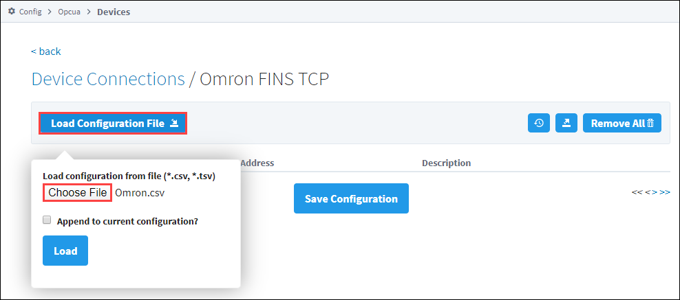
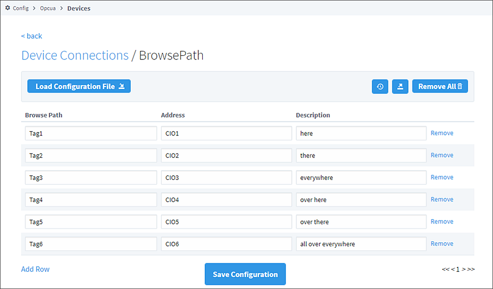
You'll see the values load onto the screen.
-
Click Save Configuration.
-
Once you save any changes made to the Tag mapping, you can view the Tags in the Connected Devices window of the Designer.
Addressing
You also have the option to manually address tags via an Ignition OPC tag in the Ignition Designer. See Ignition OPC UA Server Node Configuration for more information.
Data Areas
| Area | Ignition Code | Omron Symbol Code | Native Size |
|---|---|---|---|
| CIO Area | CIO | Int16/UInt16 | |
| Work Area | WR or W | W | Int16/UInt16 |
| Holding Bit Area | HR or H | H | Int16/UInt16 |
| Auxiliary Bit Area | AR or A | A | Int16/UInt16 |
| Timer Area | TIM or T | T | Int16/UInt16 or Bool |
| Counter Area | CNT or C | C | Int16/UInt16 or Bool |
| Index Register Area | IR | IR | Int32/UInt32 |
| Data Register Area | DR | DR | Int16/UInt16 |
| DM area | DM or D | D | Int16/UInt16 |
| EM area | EM or Exx | E | Int16/UInt16 |
EM Area
Use EM for the current bank, or Exx for bank xx, where xx is 2 hex digits. Valid banks are E00 through E18 (25 total).
Data Types
- Bit
- Bool
- Int16
- Int32
- Int64
- UInt16
- UInt32
- Float
- Double
- String
- BCD16
- BCD32
Data Type Modifiers
| Modifier | Order |
|---|---|
| @BE | Big Endian Byte Order (default when not specified) |
| @LE | Little Endian Byte Order |
| @HL | High-Low Word Order |
| @LH | Low-High Word Order (default when not specified) |
Examples
Syntax Example
Items in curly brackets {} are optional.
Below is an example OPC Item path, representing how to manually specify an address in the device.
ns=1;s=[DeviceName]Area{<DataType>}Offset{.Bit}
When typing Addresses in using the Device's Address page on the gateway, the syntax looks like the following:
Area{<DataType>}Offset{.Bit}
More Examples
| Item Path (OPC UA NodeId) | FINS Request |
|---|---|
| CIO0 | An Int16 at offset 0 in CIO area. |
| CIO<Int32>1 | An Int32 at offset 1 in CIO area. |
| CIO<Int64>3.0 | Bit 0 of an Int64 at offset 3 in CIO area. |
| CIO<Int64@HL>3 | An Int64 at offset 3 in CIO area in High-Low word order. |
| TIM0 | Present Value (16-bit) of Timer at offset 0. |
| TIM<Bool>0 | Completion Status (Bool) of Timer at offset 0. |
| CNT0 | Present Value (16-bit) of Counter at offset 0. |
| CNT<Bool>0 | Completion Status (Bool) of Counter at offset 0. |
| DR0 | An Int32 at offset 0 in DR area (32-bit by default). |
| DR<Int64>0 | An Int64 at offset in DR area. |
| CIO<Int16[3]>0 | An Int16 array of size 3 at offset 0 in CIO area. |
| CIO<Int16[3]>0[1] | Element 1 of an Int16 array of size 3 at offset 0 in CIO area. |
| CIO<String10>0 | String of up to length 10 (string length in bytes) at offset 0 in CIO area. |
| E001000 | An Int16 from EM bank 0 at offset 1000. |
| E00<Int16>1000 | Also an Int16 from EM bank 0 at offset 1000, but with the an explicit DataType to make the address look less confusing. |
| E001000 | An Int16 from EM bank 0 at offset 1000. |
| TIM0 | Present Value (16-bit) of Timer at offset 0. |
| TIM<Bool>0 | Completion Status (Bool) of Timer at offset 0. |
Ignition OPC UA Server Node Configuration
You can also create OPC Nodes in Ignition’s OPC UA server manually via a CSV file on the Ignition Gateway itself with the following settings:
- File Name: tags.csv
- File Location:$ignitionHome/data/opcua/devices/$deviceName
- File Format: Comma separated value file with the following columns:
- Browse Path
- Address
- Description
Example File
Tag1, CIO0, "First tag"
Foo/Tag2, CIO1, "Second tag, in a folder"
Foo/Bar/Tag3, CIO2, "In a couple of folders"
Use quotes on the description when it contains a comma (or whenever you like).
When adding or making changes to this file, a restart of the device is necessary for the changes to be picked up. This is done by editing the device and clicking Save.