IEC 61850 Driver
IEC 61850 is a protocol used for power systems that need to send control signals to different types of intelligent electronic devices (IEDs) defined in a substation. It is similar to the structure of the DNP3 protocol where a single station host can become a bridge to a web of other devices without taxing the network too much. For a more in-depth overview of IEC61850 standards and considerations, refer to the Understanding IEC61850 Knowledge Base article.
The Ignition driver acts as a 61850 Manufacturing Message Standard (MMS) Client. The IEC 61850 driver does NOT support Generic Object Oriented System Event (GOOSE) or Sampled Values (SV) protocols. Check your documentation to see whether your device supports IEC 61850.
The IEC 61850 driver only works on Windows and Linux (x64 distributions). ARM chips and macOS platforms are not currently supported.
In addition, the driver requires a modern version of the Visual C++ Redistributable. Read our technical advisory for more details: https://support.inductiveautomation.com/hc/en-us/articles/13897307938829
Connecting to a Device
Ignition's IEC 61850 driver can connect directly to any devices that support Ethernet communication through a substation host. It is important to make a new device connection for each of the substation device’s IEDs, since only one can be selected per connection.
-
Go to the Config section of the Gateway Webpage.
-
Scroll down and select OPC UA > Device Connections.

-
Click on Create new Device.
-
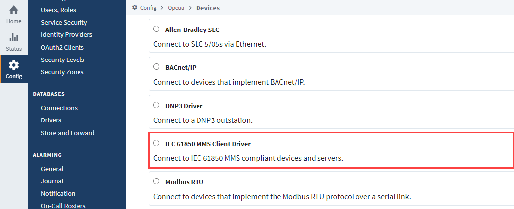
Scroll down to select the IEC 61850 MMS Client Driver and click Next at the bottom of the page.
-
Enter a desired name into the Name field. In this example, we will be entering IEC61850.
-
Enter the IP address or hostname of the device you are connecting to in the Hostname field. All other default settings can be left as is.
-
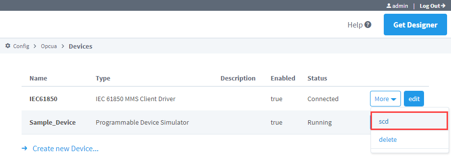
Click Create New Device. The OPC UA > Devices Connections page now lists the IEC 61850 MMS Client Driver. The Status column will show Connected or Idle, depending on the status of the device.
-
On the connected driver, IEC61850 in this example, and click More > scd.
noteSubstation Configuration Description (SCD) files grant user control of transfer device descriptions and communication parameters. This file format is the only accepted System Configuration Language (SCL) file type. It is generally recommended to use an SCD file if you intend to limit the request size and visibility of access points during OPC browsing. This will effectively reduce the load against the substation device. Without an SCD file, any device connection restart will request all defined Logical Nodes from your defined IED for OPC browsing, which can become network-traffic heavy.
However, because of how Ignition treats device attributes we recommend always using an SCD file, as it may not be possible to resolve associated quality or timestamp values without it.
-
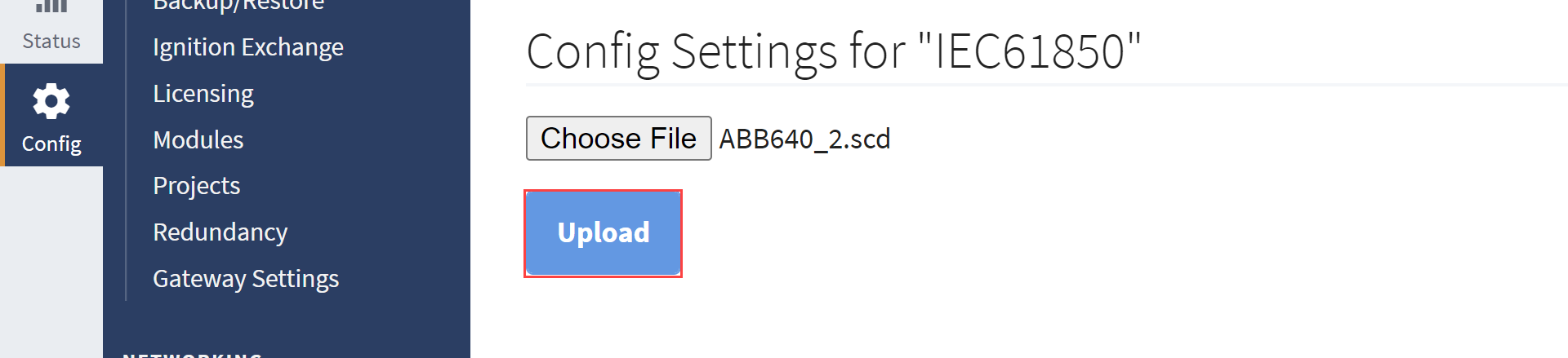
Click Choose File.
-
Locate your SCD file and select it for upload.
-
Click Upload.
-
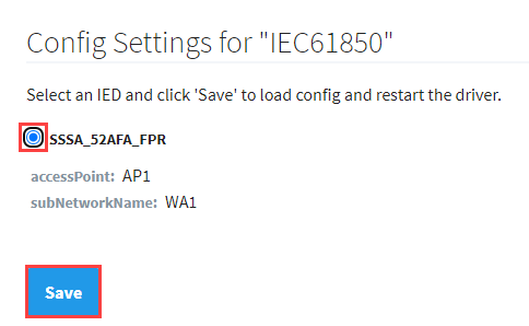
Select the IED you want to request for reports.
noteReturning to step 9, the selected IED will now display in the IED Name field and the accessPoint information will now display in the Access Point Name field for the SCL File Settings section of the advanced properties.
-
Click Save.
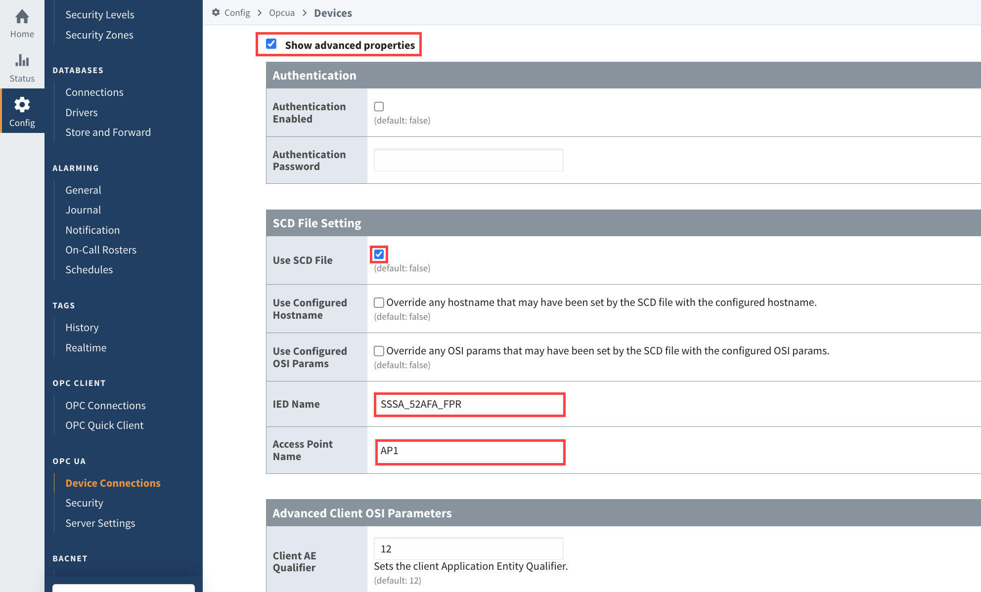
infoThe advanced properties will now show the saved SCD file settings. Checking the Show advanced properties box on the Device > edit page will display the settings. Use SCD File will be checked, and IED Name and Access Point Name will match the selected upload config settings. You can use these settings to verify correct configuration or further tweak your SCD file.
Use the OPC Quick Client to Confirm Report Statuses
Once you've established a device connection, you'll likely be looking to enable a report so it may be helpful to check the device data before opening your Designer. The OPC Quick Client can be a useful tool for checking report statuses or for troubleshooting purposes. Navigate to OPC Client > OPC Quick Client to access the Ignition OPC UA Server folder and locate your IED under the Devices folder. The configured device data is stored in three main folders:
- Model: The Model folder contains logical nodes that can be directly polled for information.
- Reports: The Reports folder includes all the available reports and attributes available for subscription.
Subscribing to any reporting control block attribute will trigger Ignition to attempt to enable the associated report via the RptEna attribute. If enabling of a report cannot be achieved you will see quality like Bad_OutOfService: The source of the data is not operational.
- Diagnostics: The Diagnostics folder contains subfolders that can help identify the status of certain aspects of the configured devices.
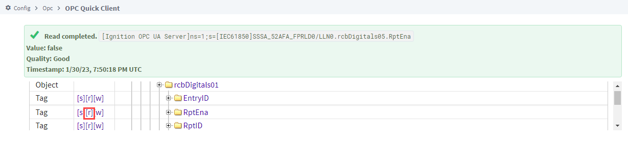
If you are unsure of your report subscription status, you can use the Read link [r] for the RptEna tag within the related Reports folder to confirm if the report is available before you try to enable it. If the value returns as True, that report is already enabled elsewhere and unavailable for use.
Few events in the IEC 61850 standard allow for writes to occur, and no write actions should be attempted on the Quick Client page. See Device Operations below for recommended practices to write back to an IED.
Device Properties
General
| Property | Description |
|---|---|
| Name | The name of this IEC61850 device connection. |
| Description | Device connection description (optional). Can be used to provide any useful information / comments about this connection. |
| Enabled | If True (checked), the connection is enabled; if False (unchecked), the connection is disabled. |
Main
| Property | Description |
|---|---|
| Hostname | The IP Address of the device. |
| Port | The port to use when connecting to an IEC61850 device, default is 102. |
| Request Timeout | Determines the maximum amount of time a request to the device will wait for a response, default is 2000. |
Advanced Properties
Authentication
| Property | Description |
|---|---|
| Authentication Enabled | Determines if a password will be provided for authenticating requests to the device, default is false. |
| Authentication Password | The password used to authenticate requests to the device, default is an empty string. |
SCD File Setting
| Property | Description |
|---|---|
| Use SCD File | Determines if a SCD file upload will be used when requesting from the device. The default value is false. |
| Use Configured Hostname | Override any hostname that may have been set by the SCD file with the configured hostname, default is false. |
| Use Configured OSI Params | Override any OSI params that may have been set by the SCD file with the configured OSI params, default is false. |
| IED Name | If Use SCD File is enabled, this field will be populated automatically with the selected IED name during the SCD File Upload. |
| Access Point Name | If Use SCD File is enabled, this field will be populated automatically with the selected IED access point information during the SCD File Upload. |
Advanced Client OSI Parameters
| Property | Description |
|---|---|
| Client AE Qualifier | Sets the client Application Entity Qualifier, default is 12. |
| Client AP Title | Sets the client Application Process Title, default is 1,1,1,999,1. |
| Client Presentation-Selector | Sets the client Presentation-Selector (P-SEL), default is 00000001. |
| Client Session-Selector | Sets the client Session-Selector (S-SEL), default is 0001. |
| Client Transport-Selector | Sets the client Transport-Selector (T-SEL). It is optionally transmitted in the OSI Transport Layer connection request (CR), default is 0001. |
Advanced Server OSI Parameters
| Property | Description |
|---|---|
| Server AE Qualifier | Sets the server Application Entity Qualifier, default is 12. |
| Server AP Title | Sets the server Application Process Title, default is 1,1,1,999,1. |
| Server Presentation-Selector | Sets the server Presentation-Selector (P-SEL), default is 00000001. |
| Server Session-Selector | Sets the server Session-Selector (S-SEL), default is 0001. |
| Server Transport-Selector | Sets the server Transport-Selector (T-SEL). It is optionally transmitted in the OSI Transport Layer connection request (CR), default is 0001. |
Misc. Advanced Settings
| Property | Description |
|---|---|
| Use Report Timestamp | Determines if the timestamp from the report will be used instead of the timestamp associated with each reported value. |
Reports
Reports can exchange monitoring information, power metering, power quality, and fault event analysis, among other data from IED servers to clients. Device data and reports are sent to the client based on user-defined device configuration through report control blocks (RCBs) and SCL files. The IEC 61850 driver supports Unbuffered/Buffered Report Control Blocks (URCB/BRCB). Remember, an RCB can only be enabled by a single device connection to the IED. This is because an RCB is blocked once a client has registered to receive a report by enabling it. Therefore, if the report is in use elsewhere, an attempted overlap could prevent connections from occurring. You will need to replicate the report on your IED if you want multiple Ignition Gateways to access the same report or leverage a Remote Tag Provider.
- Buffered Reports: Reports are buffered by the IED in case a connection to the client is interrupted so that report data is still available to the client when the connection resumes.
- Unbuffered Reports: Information is not stored during a connection loss, so any data that may have been sent during the lost connection time is not available. Reporting begins again after the connection has resumed.
localdb.autobackup.delay property, changed from 2 minutes to 60 minutes. This update eliminates the need to modify the autobackup trigger time, and in many cases, the autobackup count as described below.When using a buffered report, the config.idb file will be frequently updated with the last report_id received. A short delay, such as 2 minutes, could cause frequent backups and paused threads during the DB backup process. Changes to this property can be made in the data/gateway.xml file and looks like the following:
<entry key="localdb.autobackup.delay">60</entry>
You can also change the localdb.autobackup.count property to 0, which will turn off this feature entirely. However, this method is not recommended.
<entry key="localdb.autobackup.count">0</entry>
Use the Tag Browser to Enable a Report
Adding a report folder in your Designer immediately enables a report and allows you to see related attributes in the Tag Browser. This process is done in the same manner as creating a tag.
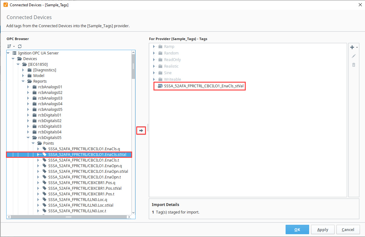
As you navigate to your desired Logical Node and Points folder, you'll notice a different format than what you might expect from a typical tag in the Tag Browser where all attributes are contained in a single tag. Attributes are listed as separate tags with their own qualified values (e.g. value, quality, and timestamps). This is because the Ignition needs to map the 61850 specification to the OPC UA model that requires an associated value, quality, and timestamp. Ignition will attempt to retrieve the q and t attributes that correspond with reported value attributes if they are available. Be sure to only add a single folder from the Points folder to your Tag Browser to avoid any issues that can occur from enabling multiple reports.
Report Attributes
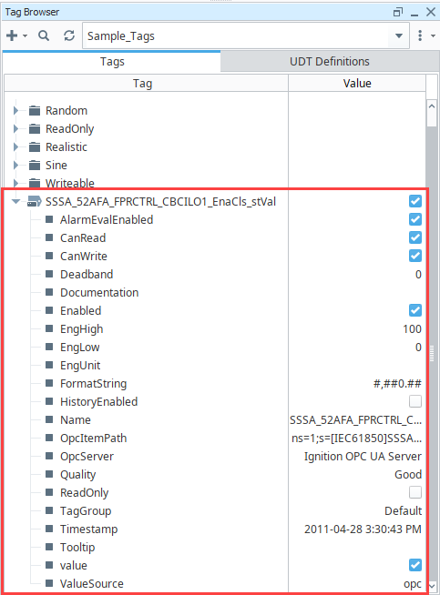
Once a specific attribute tag has been added in the Connected Devices window, you'll see your enabled report data in the Tag Browser. You can further curate this data by deleting unwanted data from the browser display.
IEC 61850 Hierarchical Data Model
Additionally, the OPC item path that Ignition uses can be isolated to identify individual attribute data because paths are built with an hierarchical data model. The data included in the path identifies the IED, logical device, logical node, data object, and attribute information. The example attribute we've been using in this section is shown below.
[SSSA_52AFA_FPR]LD0/LLN0.rcbDigitals05$SSSA_52AFA_FPRCTRL/CBCILO1.EnaCls.stVal
- IED: SSSA_52AFA_FPR
- Logical Device: LD0/LLN0
- Logical Node: rcbDigitals05$SSSA_52AFA_FPRCTRL/CBCILO1
- Data Object: EnaCls
- Attribute: stVal
Disable a Report
Deleting all Points from the Tag Browser in your Designer and/or deleting all report point subscriptions from the OPC Quick Client page will disable a report. You can confirm a report is successfully disabled by using the read from link [r] for the corresponding RptEna tag on the OPC Quick Client page.
Additionally, if a device is disabled while a subscription is still active, the subscription status code will show Uncertain_LastUsableValue instead of the good value.
Device Operations
The IEC 61850 driver supports certain system functions to control operations and perform file services. These functions can be used to discover object data, test or maintain desired statuses, and modify device files. Check out the system.iec61850 page for complete function information.
Control Functions
The supported IEC 61850 system control functions are getControlParams, Select, Operate, and Cancel. The getControlParams function returns a list of report control names and their attributes contained in the configured IEC 61850 device. Having a function to collect this data in the moment is useful for many instances, including to provide the required params keys for the Select, Operate, and Cancel functions if they are otherwise unknown.
The type of control model (ctlModel) defines how to use the Select (if applicable) and Operate control functions to write to the connected 61850 device when possible. A Status-only type means you cannot perform any operation actions. Direct types allow an immediate change to an access point using the Operate function only. Select before Operate (SBO) types require use of the Select function to confirm a chosen access point before the Operate function will run. Control model types are represented by the following values:
- 0: Status-only
- 1: Direct-with-normal -security
- 2: SBO-with-normal-security
- 3: Direct-with-enhanced-security
- 4: SBO-with-enhanced-security
The Cancel function will clear a selection of an SBO type control if an operate command is not desired to be executed on the selected control.
Safety Considerations
When working with the IEC 61850 system control functions, it's crucial to understand the potential safety implications. Misuse of these functions can lead to unintended operations and potentially catastrophic results for a high voltage substation.
The Check parameter associated with system.iec61850.getControlParams is of critical importance for safety. Inside the Intelligent Electronic Device (IED) itself, there are logical nodes for interlocking and synchronizing, named Control Interlock (CILO) and Synchrocheck (RSYN). If the Check parameter is 00, the IED will ignore CILO and RSYN and execute the command even if there is an interlock activated or the grid is not synchronized with the generator speed. The results of not knowing this can be catastrophic for a high voltage substation. It is crucial for an integrator to be aware of this.
The system.iec61850.select function is used to confirm a chosen access point before the Operate function will run. This is especially important for Select Before Operate (SBO) type controls. Misuse of this function can lead to unintended operations. Always ensure that the 'Check' parameter is properly set and understood before using this function, as it can influence the behavior of the Control Interlock (CILO) and Synchrocheck (RSYN) logical nodes in the Intelligent Electronic Device (IED).
The system.iec61850.operate function is used to write to the connected 61850 device when possible. However, it should be used with extreme caution. For Direct types, it allows an immediate change to an access point. For Select Before Operate (SBO) types, it should only be used after the Select function has confirmed the access point. Always ensure that the Check parameter is properly set and understood before using this function, as it can influence the behavior of the Control Interlock (CILO) and Synchrocheck (RSYN) logical nodes in the Intelligent Electronic Device (IED).
The system.iec61850.cancel function will clear a selection of a Select Before Operate (SBO) type control if an operate command is not desired to be executed on the selected control. This function can be used as a safety measure to prevent unintended operations. Always ensure that the Check parameter is properly set and understood before using this function, as it can influence the behavior of the Control Interlock (CILO) and Synchrocheck (RSYN) logical nodes in the Intelligent Electronic Device (IED).
File Functions
The supported IEC 61850 system file functions are listFiles, readFile, and writeFile. These functions allow users to obtain a list of files present on configured devices, and transfer IED files between remote IED servers and local paths. Note that local paths for file functions are local to the Gateway. For example, if these functions get used on a Perspective page, the file will be downloaded to the Gateway, not the client where the browser is running.