Mitsubishi TCP Driver
The Mitsubishi TCP driver provides a user interface in the Gateway where you can create, import, or export addresses when connected to devices that support the MELSEC protocol. After setup, configured tags will be browsable in the OPC Browser of the Designer with read/write access. Supported Hardware Series include:
- iQ-R
- iQ-F (FX5U)
- Q
- L
- New in 8.1.31F (FX3)
Connecting to a Mitsubishi Device
Before you can connect your Mitsubishi device to this driver, your GX Works software settings must meet certain requirements. Configuring GX Works will also provide information needed during the driver connection process, such as Hostname and Port.
To connect a Mitsubishi Device:
-
Navigate to Config > OPC UA > Device Connections on the Gateway Webpage.
-
On the Devices page, click on Create new Device.
-
Select Mitsubishi TCP, and click Next.
-
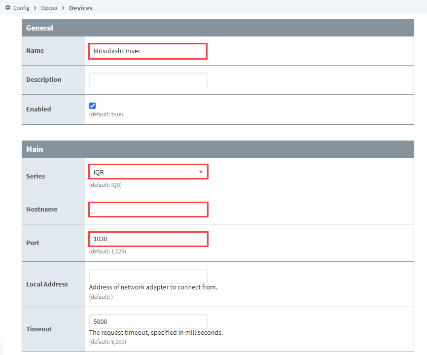
Fill in the Name field. Entering a description is optional.
-
Select the MELSEC series you will be connecting to using the dropdown. Options include iQR, iQF, Q, and L.
cautionBe sure to select the correct device type when connecting to avoid causing an error condition on the device.
-
Enter the device hostname in the Hostname field.
-
Enter the device port in the Port field.
-
Enter the local address of the network adapter to connect from. This is necessary if you have multiple network cards and you need to specify the particular network card that has PLC access.
-
Leave the default values in the remaining fields.
-
Click Create New Device.
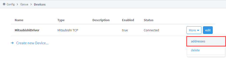
The Devices page now displays the Mitsubishi TCP device is successfully connected.
Device Settings
General
| Property | Description |
|---|---|
| Name | Device name. |
| Description | Device description. |
| Enabled | If true, attempt connection to the device, default is true. |
Main
| Property | Description |
|---|---|
| Series | The series of the Mitsubishi device. Default is iQR. |
| Hostname | The IP Address of the device. |
| Port | The port the device is listening on. |
| Local Address | Address of network adapter to connect from. |
| Timeout | The request timeout, specified in milliseconds with a valid range from 0 to 16383750. Default is 5000. |
Request Optimization
| Property | Description |
|---|---|
| Max Gap Size | The maximum address “gap” to span when optimizing requests to contiguous address locations. Increasing the max gap size will reduce the number requests but increase the amount of data requested. Default is 0. |
| Write Priority Ratio | The number of write requests to execute for every read request when an abundance of both types are queued up for execution. Default is 5. |
Access Route Settings
| Property | Description |
|---|---|
| PC Number | The network module station number of an access target. Default is 255. Note: The station number that should be used as the PC number will vary depending on how your PLC network is set up. For instance, when accessing a station via network, the PC number is the station number of the access target. However, when accessing a multi-drop connection station via network, the PC number is the station number of the relay station. |
| Network Number | The network number of an access target. Default is 0. |
| Request Destination Module I/O Number | The start input/output number of a multi-drop connection source module, or the CPU module of a multiple CPU system. Default is 1023. |
| Request Destination Module Station Number | The station number of an access target module when accessing a multi-drop connection station. So, when the PC Number is set to the station number of the relay station, this property should be set to the target station number. Default is 0. |
Adding Addresses
You can add addresses through a few different options on the Gateway or in the Designer.
Addressing on the Gateway
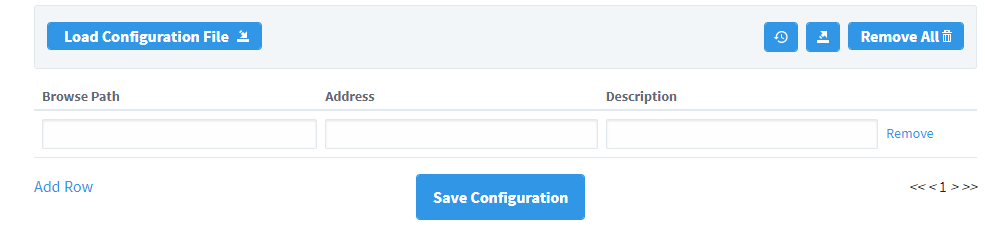
The Mitsubishi addresses page on the Gateway allows entering Browse Path and Address information individually, importing user-created CSV files containing a list of addresses, and importing a GX Works CSV file. Even if you are planning to import multiple addresses using a CSV file, it’s recommended to first enter a single tag address to test if your connection is working as expected. The addresses page has three areas of information:
- Browse Path: This represents the browse path for the OPC UA client.
- Address: This is the device, offset, and additional specifications to find desired values.
- Description: This is an optional field to help in identifying displayed values.
To access the addresses page:
-
Navigate to the Config > OPC UA > Device Connections.
-
Click the More dropdown and choose addresses on your Mitsubishi device.
Adding Individual Address Rows
To manually enter addresses:
-
Click Add Row to populate rows for address information.
-
Enter Browse Path field and Address field information. Enter Description information as desired.
noteAll components are case-insensitive.
-
Continue adding rows and address information until you’ve added all the addresses you want to be available as tags.
-
Click Save Configuration when you are finished.
Importing and Exporting
To import a CSV file:
-
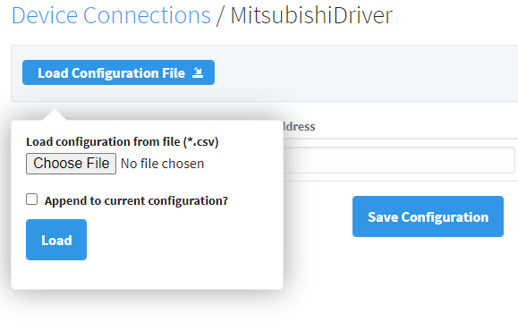
Select Load Configuration File on the device address page.
-
Select Choose File.
-
Locate the CSV file you want to upload and select it to open.
cautionMake sure a comma separates column information, and if your Description column includes commas, use quotes to prevent misinterpretations when uploading.
-
Select the Append to current configuration box if you already have addresses listed and you want to add on to them. Leave unchecked if you want to replace existing rows.
-
Click Load.
cautionIf an existing address shares a tag name with an address imported by the CSV file, it will be replaced with the imported address.
-
Click Save Configuration.
To export the address list from the Gateway page, simply use the Export Configuration ![]() icon to download.
icon to download.
Addressing in the Designer
You also have the option to address tags via an Ignition OPC tag in the Ignition Designer. See Ignition OPC UA Server Node Configuration for more information. As opposed to adding addresses on the Gateway, the device needs to be specified here.
ns=1;s=[DeviceName]Area{<DataType{[array]}>}Offset{.Bit}
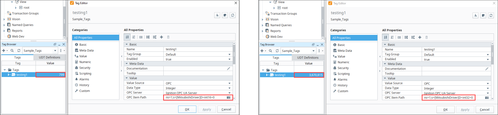
Regardless of if the address path was entered on the Gateway and added as a tag, or entered directly in the Designer, you can continue to edit the item path in the Tag Editor if needed. The example below shows how changing the OPC Item Path data type from int16 to int32 instantly changes the tag value from 799 to 3,670,815.
Determining Addresses
The Mitsubishi driver requires Area and Offset address components, but also allows many optional specifications. It’s important to know where the optional components must be placed in your address to properly connect. The example syntax below shows how optional data type (including modifiers) and array specifiers are listed before the Offset specification, and the optional array element index and bit index must be listed after the Offset specification.
Area{<DataType{[array]}>}Offset{.Bit}
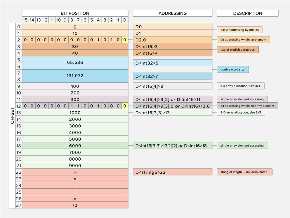
The image below demonstrates how different address specifications correspond with a Mitsubishi data register. The Description column functions the same way as it does on the Mitsubishi Driver addresses page to detail where the address is looking for data. The following syntax sections on this page provide an in-depth breakdown on how to find and enter addresses similar to the ones shown in these examples.
Areas
On this page, and for the Mitsubishi driver, the term Area refers to the accessible Device Items. See the Area table below for potential device names and their related keywords and types.
MELSEC-Q/L, iQ-F, and iQ-R
The following table shows the MELSEC-Q/L, iQ-F and iQ-R series devices, keywords, and native types recognized by the driver. Extended Data Registers and Extended Link Registers are currently not supported.
| Device Name | Keyword | Type |
|---|---|---|
| Special Relay | SM | Bit |
| Special Register | SD | Word |
| Input | X | Bit |
| Output | Y | Bit |
| Internal relay | M | Bit |
| Latch relay | L | Bit |
| Annunciator | F | Bit |
| Edge relay | V | Bit |
| Link relay | B | Bit |
| Step relay | S | Bit |
| Data register | D | Word |
| Link register | W | Word |
| Timer (Contact) | TS | Bit |
| Timer (Coil) | TC | Bit |
| Timer (Current value) | TN | Word |
| Long timer* (Contact) | LTS | Bit |
| Long timer* (Coil) | LTC | Bit |
| Long timer* (Current value) | LTN | Double word |
| Retentive timer (Contact) | STS | Bit |
| Retentive timer (Coil) | STC | Bit |
| Retentive timer (Current value) | STN | Word |
| Long retentive timer* (Contact) | LSTS | Bit |
| Long retentive timer* (Coil) | LSTC | Bit |
| Long retentive timer* (Current value) | LSTN | Double word |
| Counter (Contact) | CS | Bit |
| Counter (Coil) | CC | Bit |
| Counter (Current value) | CN | Word |
| Long counter* (Contact) | LCS | Bit |
| Long counter* (Coil) | LCC | Bit |
| Long counter* (Current value) | LCN | Double word |
| Link special relay | SB | Bit |
| Link special register | SW | Word |
| Direct access input | DX | Bit |
| Direct access output | DY | Bit |
| Index register (Index register) | Z | Word |
| Index register* (Long index register) | LZ | Double word |
| File register (Block switching method) | R | Word |
| File register (Serial number access method) Note: This register is not available for Q/L series with Ignition versions 8.1.43 and earlier. | ZR | Word |
| Refresh data register* | RD | Word |
*Not available for Q/L series
MELSEC-F
The following table shows the MELSEC-F series devices, keywords, and native types recognized by the driver.
| Device Name | Keyword | Type |
|---|---|---|
| Input | X | Bit |
| Output | Y | Bit |
| Internal relay | M | Bit |
| Step relay | S | Bit |
| Data register | D | Word |
| Timer (Contact) | TS | Bit |
| Timer (Current value) | TN | Word |
| Counter (Contact) | CS | Bit |
| Counter (Current value) | CN | Offsets 0-199: Word Offsets 200-255: Double Word |
| File register (Block switching method) | R | Word |
Offsets
A simple example of reading a bit would be D0.0, which reads the bit0 of int16 at offset 0. You can also read bits within array elements that represent scalar values following the same addressing format. To read the bit 0 of element 0 of an array of length 4 at offset 0 would be D<int16[4]>0[0].0.
Depending on the PLC series and bit area combination, offsets must be specified in octal, hex, or decimal. The following table lists the combinations that have a specification other than decimal.
| iQ-R | iQ-F | Q | L | F (FX3) | |
|---|---|---|---|---|---|
| X | Hex | Octal | Hex | Hex | Octal |
| DX | Hex | N/A | Hex | Hex | N/A |
| Y | Hex | Octal | Hex | Hex | Octal |
| DY | Hex | N/A | Hex | Hex | N/A |
| B | Hex | Hex | Hex | Hex | N/A |
| SB | Hex | Hex | Hex | Hex | N/A |
| W | Hex | Hex | Hex | Hex | N/A |
| SW | Hex | Hex | Hex | Hex | N/A |
Note that leading zeroes and lowercase hex characters are accepted. For example XF would be read the same as X0f.
Optional Data Types
The Mitsubishi driver supports reading/writing data types larger than the area’s native type by combining bytes from adjacent offsets into a single value. For example, each Data Register (D) point is natively a word (16-bit), but reading D<int32>0 requests bytes for D0 and D1 and combining the bytes into a signed 32-bit value.
The Mitsubishi driver does not support reading/writing data types smaller than the area’s native type. For example, each Long Index Register (LZ) point is a double word (32-bit) which means LZ<int16>0 and LZ<uint16>0 cannot be specified.
Some areas in particular cannot be combined and specific data types corresponding to its native type must be specified:
- Any areas having a native type of Bit
- Any area having to do with Current value, such as:
- TN
- LTN
- STN
- LSTN
- CN
- LCN
When specifying a string data type, the length of the string must also be specified on the address. For example, D<string10>0 requests a string of up to 10 characters at offset 0 in the data register device.
If the length of the string is less than the address string length, it will be padded with null characters. For example, writing “hello” to D<string10> is equivalent to writing “hello\0\0\0\0\0” where “\0” are null characters. If the length of the string is more than the address string length, it will be truncated to the address string length. For example, writing “hello world!” to D<string10> is equivalent to writing “hello worl”.
The string length will be automatically rounded up to the nearest even value. This is because two characters are stored inside a word. For example, D<string9>0 will be treated as D<string10>0.
The following data types are recognized by the driver:
- Bool
- Int16
- Int32
- Int64
- UInt16
- UInt32
- UInt64
- Float
- Double
- Changed in 8.1.31String (to use for ASCII characters)
- New in 8.1.31Wstring (to use for Unicode characters)
If the data type is omitted, a default data type will be used depending on the area’s native type:
| Area Native Type | Default Data Type |
|---|---|
| Bit | bool |
| Word | int16 |
| Double word | int32 |
The following optional data type modifiers are recognized by the driver:
| Attribute | Order |
|---|---|
| @BE | Big Endian Byte Order |
| @LE | Little Endian Byte Order (default when not specified) |
| @HL | High-Low Word Order (default when not specified) |
| @LH | Low-High Word Order |
Optional Arrays
Arrays are a concept created within the driver representing contiguous blocks of memory starting from an offset. For example, instead of reading D<int16>0 through D<int16>8, you can create an array of the same values. The number of elements in an array are determined by multiplying the array dimensions. So reading D<int16[3, 3]>0 is a length of 3x3 where the start offset is 0 and the last offset is 8.
Similarly, reading an element within an array is equivalent to reading a single address. For example, you can see in the table below that reading D<int16[3, 3]>0[1][2] is equivalent to reading D<int16>5.
| D[0][0] = D<int16>0 | D[0][1] = D<int16>1 | D[0][2] = D<int16>2 |
| D[1][0] = D<int16>3 | D[1][1] = D<int16>4 | D[1][2] = D<int16>5 |
| D[2][0] = D<int16>6 | D[2][1] = D<int16>7 | D[2][2] = D<int16>8 |
Large arrays should be used with caution. If an array read/write request is too large to fit into a single request, it will be broken up into multiple non-atomic sequential requests. Splitting requests when writing can result in the first send of the write requests creating new values and the remaining write requests failing. Similarly, if read requests are sent separately the resulting array may contain stale points.
Determining if an array is too large to be sent at the same time depends on how the array is optimized. Optimization refers to the process of minimizing the number of requests sent to the PLC by batching together device points with the goal to fit as many points as possible into a single request before splitting it off into multiple requests. Request optimization happens automatically when points are read or written to at the same time.
Optional Bit Index
Bit indexing can be specified on any integer data type to retrieve a boolean value at a bit position. Addresses with a bit index are read-only and any attempts to write to them will result in a Bad_NotSupported error due to the MELSEC protocol.
A bit index cannot be specified for the following:
- Non-integer data types (bool, float, double, and string)
- Non-scalar addresses (arrays)
GX Works Configuration
GX Works is the programming software designed for Mitsubishi PLCs. Before you can use the Mitsubishi driver, some configurations need to be made in GX Works when connecting to MELSEC-Q/L, iQ-F and iQ-R series devices with the Mitsubishi driver. These instructions are written for GX Works3. GX Works2 has slightly different settings but should in general resemble the following setting requirements.
- Under the navigation tab, locate Parameter > CPU > Module Parameter > Basic Settings > Own Node Settings.
- Set Enable/Disable Online Change to Enable All (SLMP).
- Set Communication Data Code to Binary.
- Navigate to External Device Configuration > Detailed Setting to add an SLMP Connection Module to the Ethernet Configuration with Protocol set to TCP.
- Make sure to also identify the IP Address and Port No. These settings are what will be used for the Mitsubishi TCP driver Hostname and Port connection fields.
- Write all changes to the PLC (Online > Write to PLC) and initiate a power cycle.
Configuring Device Points
Some areas or offsets within an area may not be accessible by default unless additional memory is allocated.
- Navigate to Parameter > CPU > CPU Parameter > Memory Device Setting > Device/Label Memory Area Setting > Detailed Setting.
- Change Points to desired size. The point allocation from all areas must not exceed the Total Device size.
- Click Apply.
- Write to the PLC (Online > Write to PLC) and initiate a power cycle.
Using GX Works3 to Troubleshoot
If you have access to GX Works3, you can use the Device/Buffer Memory Batch Monitor feature to test or troubleshoot your connection. This can be found under Online > Monitor > Device/Buffer Memory Batch Monitor. Type in the device keyword with an offset and hit enter to begin monitoring values.
GX Works also has an Ethernet Diagnostics tool which is useful for determining the status of the connection as well as other information like IP Address, Port No, and Latest Error Code. To access this tool, navigate to Diagnostics > Ethernet Diagnostics.
FX Configurator
FX Configurator is the required software for initial PLC setup when connecting to MELSEC-F series devices. Once you have created an FX3U model GXDeveloper project, complete the following configuration to begin making device connections.
- Click Tools from the menu bar to select FX Special Function Utility > FX Configurator-EN.
- Enter the minimum required FX3U-ENET configuration information.
- Open the Operational Settings under Ethernet Module Settings and set the settings to the following:
- Communication Data Code: Binary code.
- Initial Timing: Always wait for OPEN.
- Input Format: DEC.
- Send Frame Setting: Ethernet(V2.0).
- TCP Existence Confirmation Setting: Use the KeepAlive.
- Select End when finished.
You can now add connections by selecting Open Settings back in the FX Configurator-EN window. These connections must set the Protocol to TCP and Fixed Buffer Communication Procedure to Procedure Exist(MC). Recommendations for the remaining settings are as follows:
- Open System: Unpassive
- Fixed Buffer: Send
- Pairing Open: Disable
- Existence Confirmation: Confirm