Programmable Device Simulator
The Programmable Device Simulator allows you to add simulator devices that act as if they are connected to a real device. It allows users to read and write Tags without any network or PLC connection.
The Programmable Device Simulator provides functionality that allows you to create your own simulator program with outputs you define. Users are able to create Tags that can be used in their own development process, thus providing the flexibility to simulate devices with a Tag structure they are building for their project. There are a number of built-in functions that will result in unique Tag outputs rather than static values. We also provide the ability to set specific values at different points of the program should the functions not provide exactly what you need.
The Programmable Device Simulator replaced the previous built-in simulators in earlier versions of Ignition, and combined the Dairy Demo, Generic and SLC simulator device connections into a single driver.
Connecting to a Programmable Device Simulator
Connecting to a Programmable Device Simulator and loading the programs are simple and will give you some values that change on their own. These simulator devices can be used for realtime values, history and alarms.
-
From the Gateway webpage, go to the Config section.
-
Scroll down and select OPC UA > Device Connections.
-
Click on Create new Device....
-
Select Programmable Device Simulator, and click Next.
-
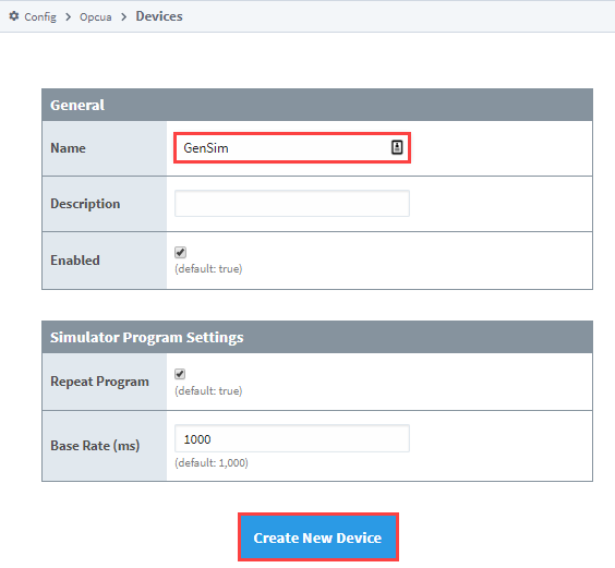
Give the device a name (i.e., GenSim), and click Create New Device button.
-
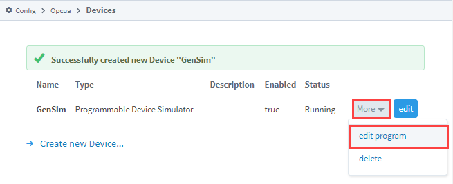
The window will refresh and you'll see your device was successfully created with a status of "Running". Now you can set the program for the simulator by clicking More > edit program.
-
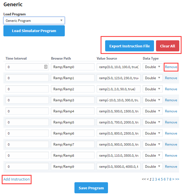
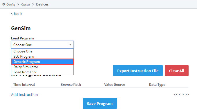
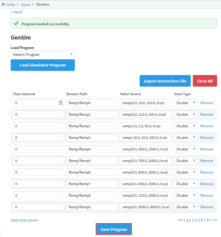
Create a program by either clicking the Add Instruction link to add a new line of instruction to the program, or loading a predefined program from the Load Program dropdown (i.e., Generic Program) and clicking the Load Simulator Program button.
-
Once you have some instructions, click the Save Program button. These instructions determine what Tags get made, and what their values are.
Simulator Settings
| Setting | Description |
|---|---|
| Repeat Program | If True, the program will repeat indefinitely, meaning that once the last defined Time Interval has been reached, the program will start over again at Time Interval 0. |
| Base Rate (ms) | The number of milliseconds determining how quickly the program should move between each Time Interval. The initial duration of the Base Rate is defined in the Program Device Simulator settings should you need this value to persist after restarts. |
Program Instructions
The simulator gets its values from a Program made up of various instructions. The program runs through the instructions in order and executes. Each Program Device Simulator contains only one program. Each instruction has a Time Interval and Tag path. If there is more than one Time Interval for a Tag, it will step through those values in order. You can alternatively have a single time Interval and a function in the Value Source field.
| Term | Description |
|---|---|
| Time Interval | Represents a “step” or point in time for the program. A program will start at interval 0, and set the Value Source on the Tag. The program will wait for a number of milliseconds (determined by the Base Rate, defined below) before moving to the new Time Interval. |
| Browse Path | The full path to the Tag you want to create in the simulator. Forward slashes are used to specify folders, as well as act as a delimiter for additional folders in the path. |
| Value Source | Determines how the value for the node at the Browse Path is generated. Either a static value or a function will be used to generate the value. |
| Data Type | The Data Type for a node. Valid types are:
|
Value Source Functions
Users are allowed to define a 'function' for the value source. This is not a Python or Expression function. Rather, the value in the cell is a string that looks like a function definition; eg., foo(x,x,x). The driver will attempt to parse the string, and then derive a value based on the function. Valid functions are in the following table.
| Function | Descriptions |
|---|---|
| sine(min, max, period, repeat) | Sine wave. The value moves between the min value and max value, and back to the min. The total duration of this wave is based on the period parameter. If no parameters are specified, then the function should produce a wave that starts at 0, reaches an upper bound of 100, and returns to 0. This series should occur over the default period ( (10 * Base Rate) * 1000 ms = 10,000 ms). |
| cosine(min, max, period, repeat) | Cosine wave. |
| square(min, max, period, repeat) | Square wave. |
| triangle(min, max, period, repeat) | Triangle wave. |
| ramp(min, max, period, repeat) | Ramp signals starts from the min value going up to max value based on the period parameter. When the value reaches its upper limit, it is reset to the min value. |
| realistic(setPoint, proportion, integral, derivative, repeat) | A realistic number generator driven by a PID system. |
| random(min, max, repeat) | Random values starting at the min value and working up to the max value. Changed in 8.1.38 For Boolean tags, the min and max parameters are unused. They are still required, but ignored. |
| list(value1, value2, etc..., valueN, repeat) | Accepts any number of parameters and walks through each value in this list. |
| qv(value, qualityCode) | Sets a value and quality code. Allows users to simulate a value with bad quality. |
| readonly(value) | Sets a static value for read only purpose. |
| Each of the functions above expect certain parameters. |
| Parameter | Description | Default Value |
|---|---|---|
| min | Minimum value for the function. | 0 |
| max | Maximum value for the function. | 100 |
| period | Represents a period of time as a number of Time Intervals. The default value of 10 represents "10 Time Intervals." | 10 |
| setPoint | The setpoint of the PID Control Loop. Also known as the desired position. | 100 |
| proportion | The proportional value of the PID Control Loop. | 1.2 |
| integral | The integral value of the PID Control Loop. | 0.06 |
| derivative | The derivative value of the PID Control Loop. | 0.25 |
| qualityCode | Allows users to set the quality on a Tag (assuming the function used contains a quality code parameter). Valid values are: Good, Bad, Uncertain. | Good |
| repeat | Does the function repeat for each time slice of the program, or does it report a single value when the instruction is run.The default value of true will ensure that a function will continue to run as long as the program itself is running. A value of false will only update a value when it reaches the specified Time Interval in the program. | true |
Example Instruction Files
Simple Function Example
| TimeInterval | BrowsePath | ValueSource | DataType |
|---|---|---|---|
| 0 | TagA | sine(0,100,10,true) | Double |
The table above shows us function usage with parameters. Because the example is using default values, it is functionally equivalent to the following:
| TimeInterval | BrowsePath | ValueSource | DataType |
|---|---|---|---|
| 0 | TagA | sine() | Double |
Running this program should yield the following results (assuming repeat is enabled):
- A Tag at root named “TagA” will be created.
- Since only a single Time Interval was defined, the program ends quickly. The delta time between the start of the program and the end should be around one Base Rate interval.
- The simulator will use a internal clock to ensure that the value reported is representative of the actual period for the function requested and if history is enabled, a full wave would be graphed.
Advanced Program Example
| TimeInterval | BrowsePath | ValueSource | DataType |
|---|---|---|---|
| 0 | TagA | sine() | Double |
| 0 | myfolder/TagB | 0 | Int32 |
| 3 | myFolder/TagB | 4 | Int32 |
| 4 | another_folder/TagC | 100 | Int32 |
| 20 | TagA | ramp() | Double |
| 30 | myfolder/TagB | 55 | Int32 |
The program above should yield the following results:
-
TagA is initialized with the Sine function.
-
TagB (which is located under myFolder in the simulator’s structure) is initialized with a value of 0.
-
TagC isn’t defined at the start, but that doesn’t matter; the program creates a TagC initially because it will exist in the device. If this is the first time the program ran, then TagC started with a value of 0. If it is the second time through, it maintains the value at the end of the program until it reaches an interval where something changes.
-
Time Interval 1. The program doesn’t state that any changes should be made, so we’re done evaluating this Time Interval.
-
Time Interval 2. Again, nothing to do here, so we wait another Base Rate duration.
-
Time Interval 3, the value on TagB to 4.
-
Time Interval 4. The value of TagC changes to 100. If this program has executed at least once before, then TagC could already have a value of 100, since this is the only entry in the program that changes the value on Tag C. However, it is possible that the user (or something else, such as a binding or script) wrote another value to this Tag. At this point, our program is setting the value back to 100
-
Time Interval 20, TagA switches to the Ramp function. This whole time it has been using the Sine function to generate some moving numbers, but now we’re telling it to use the Ramp function, which change the value (starting with the minimum value for the function) and uses a different method to determine its value.
-
Time Interval 30. The value of TagB changes to 55.
-
We’re now at the end of the program. If Repeat was enabled, we’ll move back to Time Interval 0 and start the whole process over again. If not, then the program ends for all Tags.
Preloaded Programs
The Programmable Device Simulator comes with preloaded programs for Generic, Dairy and SLC simulators, as well as the ability to load from a CSV.
When loading any of the default programs (Generic, Dairy, or SLC), the item paths on the tags generated will contain a _Meta: prefix. This prefix exists for legacy purposes to ensure that users who replace simulators created in 7.x with the new programmable simulator will not have to recreate tags.
However, this also means that if you later export these tags as a CSV, the _Meta: prefix is removed since it is not clearly shown in the browse path. This means that once you are done adding or removing tags in the exported CSV and want to import again, the old tags may no longer work. To fix the old tags, you can either recreate the OPC tags or manually add _Meta: before the value set in the Browse Path column.
ns=1;s=[Testing]_Meta:Writeable/Agitator1Mode
Generic Simulator Program
The Generic Simulator Program provides a variety of Tags that offer different data types and value generation styles. For example, there are ramps, sine waves, and random values. Additionally, there is a set of static writable Tags whose values will persist while the device is running.
Dairy Simulator Program
The Dairy Simulator Program has a ControlLogix like structure with Compressor, Tank, Motor Tags and more. The folders are split into an Overview and Refrigeration section with Tags multiple levels deep that mimic a UDT in a ControlLogix device.
SLC Simulator
The SLC Simulator Program creates a simple device whose address structure mimics a basic SLC structure. These Tags are readable and writeable.
Load From CSV
The Load from CSV option allows you to select a CSV file to load a predefined program from. The CSV file must have four columns in a specific order (Time Interval, Browse Path, Value Source, Data Type), with each row representing a different instruction in the program.
Meta Tags
Each Programmable Device Simulator will have Meta Tags that allow users to interact with the program from the Designer/Session/Client. All Tags will be listed under the parent folder [Controls] within the device. Altered Meta Tag values do not persist after restart.
| Term | Description |
|---|---|
| Base Rate | The number of milliseconds determining how quickly the program should move between each Time Interval. The initial duration of the Base Rate is defined in the Program Device Simulator settings should you need this value to persist after restarts. |
| Pause | Setting this Tag to 'True' will stop the program at its current Time Interval. Setting it back to 'False' will cause the program to resume from that point. |
| Program Counter | A count that tracks the Time Interval of the currently running program. This counter continues to increment for the duration of the program and resets when a program repeats. |
| Repeat | If True, the program will repeat indefinitely, meaning that once the last defined Time Interval has been reached, the program will start over again at Time Interval 0. |
| Reset | If True, the program is immediately reset to Time Interval 0 and the value will immediately change back to' False.' |
Export Instruction File
The ability to create custom instructions in the driver was added providing an opportunity to create a custom simulator device. You have the option of exporting the instruction file to a CSV formatted file and loading it once it's modified. You also have the ability to add and remove individual instructions. Clear All removes all instructions in the program.