Allen Bradley Connection Paths
Connections to ControlLogix, CompactLogix, PLC-5, MicroLogix and SLC Allen-Bradley processors through a ControlLogix Gateway require a connection path. The connection path is unique to your setup and is dependent on what modules the connection is being routed through. However, each connection path follows a basic set of rules outlined below.
Follow the Path
A connection path is a path that when followed leads from the ControlLogix gateway to a processor residing in a numbered slot of a chassis somewhere on site. You only have to build the connection path as you go.
Setting Up the Device Connection
The first connection point between Ignition and the device is a ControlLogix Ethernet module such as an ENET, ENBT, or EN2T module. This means that the while the driver type used is the same type as the PLC you want to connect to, the hostname actually needs to point to the ControlLogix Gateway. The connection path is then followed to go out of the ControlLogix Gateway and into the PLC you are connecting to.
You need to have 6 numbers/entries to specify the connection path. The way you find each number is described in the following table:
| Number | Description |
|---|---|
| 1st Number | Is 1 and means move to the back plane. |
| 2nd Number | Is the slot number of the module you want to move to. |
| 3rd Number | Is the exit port or channel of that module that you want to exit through. |
| 4th Number | Is the address of entry point to the next module (DH+ Station Number/ControlNet Address/IP Address of ethernet module). |
| 5th Number | Is 1 and means move to the back plane (from this 5th Number, it starts repeating as the 1st Number). |
| 6th Number | Is the processor slot number OR the slot number of the module you want to move to. |
The process of coming up with these numbers may sound complicated at first but after some practice it gets easier.
Examples
Below there are a few examples that go over the differences with using specific modules to route the connection. Note that typically, the end result PLC does not matter. So while the example may show connecting to a PLC5 through ControlNet, the the PLC5 could easily be swapped out with another PLC, and the connection path would remain the same. The big change when using different end result PLCs is what device driver to use for the connection.
Understanding how the Connection Paths are built listed above is important to understand the specifics of using different modules in the examples below.
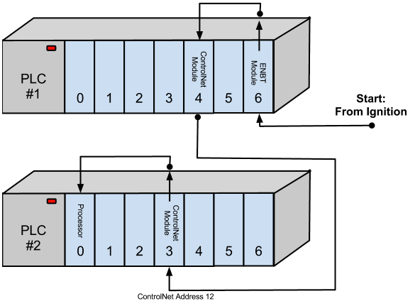
Connecting to a PLC Through ControlNet
The example below connects to a PLC5 using ControlNet that has a connection path of 1,4,2,12,1,0 going from PLC 1 to PLC 2. The device driver is the Allen-Bradley PLC5, and the hostname is the IP address of the ControlLogix Gateway (PLC #1).
| Number/Entry | Description |
|---|---|
| 1 | Move out of ENBT Module to the backplane. |
| 4 | Move to ControlNet Module in Slot 4. |
| 2 | Move out ControlNet Port. |
| 12 | Move in ControlNet Module at ControlNet Address 12. |
| 1 | Move out of ControlNet to the backplane. |
| 0 | Move to the Processor in Slot 0. |
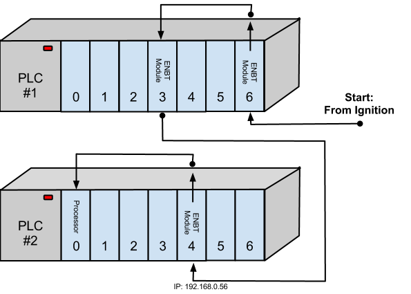
Connecting to a PLC Using ENBT
The example below connects to a ControlLogix using ENBT that has a connection path of 1,3,2,192.168.0.56,1,0 going from PLC 1 to PLC 2. The device driver is the Allen-Bradley ControlLogix, and the hostname is the IP address of the ControlLogix Gateway (PLC #1).
| Number/Entry | Description |
|---|---|
| 1 | Move out of ENBT Module to the backplane. |
| 3 | Move to ENBT Module in Slot 3. |
| 2 | Move out the Ethernet Port. |
| 192.168.0.56 | Move in EBNT Module at IP Address 192.168.0.56. |
| 1 | Move out of EBNT to the backplane. |
| 0 | Move to the Processor in Slot 0. |
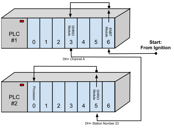
Connecting to a ControlLogix Using Data Highway Plus (DH+)
The example below connects to a ControlLogix using Data Highway Plus that has a connection path of 1,3,2,23,1,0 going from PLC 1 to PLC 2. The device driver is the Allen-Bradley ControlLogix, and the hostname is the IP address of the ControlLogix Gateway (PLC #1).
| Number/Entry | Description |
|---|---|
| 1 | Move out of ENBT Module to the backplane. |
| 3 | Move to DHRIO Module in Slot 3. |
| 2 | Move out DH+ Channel A. |
| 23 | Move in DH+ Station Number 23. |
| 1 | Move out of DHRIO Module to the backplane. |
| 0 | Move to the Processor in Slot 0. |
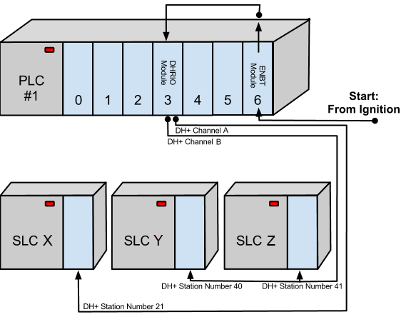
Connecting to Multiple SLCs Using Data Highway Plus (DH+)
The example below connects to 3 different SLC using Data Highway Plus. Each SLC connection would have their own device connection, each with a unique connection path.
The connection paths are:
- SLC X 1,3,2,21
- SLC Y 1,3,3,40
- SLC Z 1,3,3,41
The device driver is the device you want to connect to (in this case, Allen-Bradley SLC), and the hostname is the IP address of the ControlLogix Gateway (PLC #1).
SLC X
| Number/Entry | Description |
|---|---|
| 1 | Move out of ENBT Module to the backplane. |
| 3 | Move to DHRIO Module in Slot 3. |
| 2 | Move out DH+ Channel A. |
| 21 | Move in DH+ Station Number 23. |
SLC Y
| Number/Entry | Description |
|---|---|
| 1 | Move out of ENBT Module to the backplane. |
| 3 | Move to DHRIO Module in Slot 3. |
| 3 | Move out DH+ Channel B. |
| 40 | Move in DH+ Station Number 40. |
SLC Z
| Number/Entry | Description |
|---|---|
| 1 | Move out of ENBT Module to the backplane. |
| 3 | Move to DHRIO Module in Slot 3. |
| 3 | Move out DH+ Channel B. |
| 41 | Move in DH+ Station Number 41. |