Legacy DNP3 Driver
The Legacy DNP3 driver, previously known as the DNP3 Driver before 8.1.36, uses the DNP3 protocol for explicit reads and unsolicited messaging to acquire data. The Legacy DNP3 driver will no longer receive continued support, updates, or fixes. For the updated driver, see DNP3 Driver.
The Legacy DNP3 driver does not support DNP3 Secure Authentication.
Data Acquisition Methods
The Legacy DNP3 driver offers two methods for acquiring data: explicit reads and unsolicited messaging.
Explicit Reads
Explicit reads are the primary method of data acquisition for the Legacy DNP3 driver.
The DNP3 Read function code is used to read data points directly. Each polling operation retrieves only the current value of each point; event data is not retrieved or processed. Explicit reads are typically used when points are addressed using the group/variation/index (gvi) syntax.
Unsolicited Messaging
Unsolicited messaging is an event-driven method of acquiring data. Instead of polling at regular intervals, the outstation automatically reports changes when they occur. The client's sampling interval does not affect the outstation, but it does affect OPC UA MonitoredItem and Subscription behavior.
OPC UA clients with MonitoredItems configured with a sampling interval of 0 will receive the full reported sequence of events for each point.
Not all outstations support unsolicited messaging, so review your device’s documentation before enabling it.
Connecting to a Device
This module requires the OPC UA module to be installed and enabled. If the OPC UA module is not installed or is disabled, this module will fault with a warning in the logs and display the state as "Faulted Missing Dependency" on the Config > Modules page.
The Legacy DNP3 driver connects to devices that support Ethernet communication through a master station. Create a separate device connection for each outstation (remote device) by setting the source and destination addresses in the device connection settings.
-
Go to the Config section of the Gateway Webpage.
-
Select OPC UA > Device Connections.

-
Click Create new Device.
-
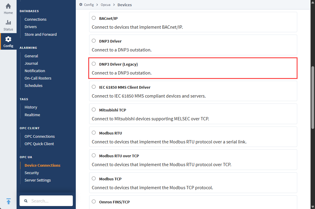
Choose Legacy DNP3 Driver, then click Next.
-
On the New Device page, enter:
- Name: Legacy DNP3
- Hostname: IP address or hostname of the device
-
(Optional) Click Show advanced properties to configure additional settings.
-
Click Create New Device. The Status will change from Disconnected to Connected or Idle.
Connection Settings
General
| Property | Description |
|---|---|
| Name | The name of this DNP3 device connection. |
| Description | An optional description for the connection. You can use this field to add any helpful comments about the connection. |
| Enabled | If checked (True), the connection is enabled. If unchecked (False), the connection is disabled. |
Main
| Property | Description |
|---|---|
| Hostname | The IP address or hostname of the device. |
| Port | The TCP port to use when connecting to the outstation. Default is 20000. |
| Local Address | New in 8.1.8 The local address to connect from when establishing a TCP connection. Leave blank to auto-select. |
| Source Address | The address of the local (master) station. Default is 3. Note: Source and Destination addresses must be reversed between Ignition and the device.
|
| Destination Address | The address of the remote (outstation) device. |
| Integrity Poll Interval | The interval at which to perform an integrity poll, in milliseconds. Default is 3,600,000. |
| Direct Operate Enabled | If true, the Direct-Operate function code is used for writes; if false, Select-Operate is used. Default is true. |
| Unsolicited Messages Enabled | If true, the outstation may send unsolicited messages. Default is false. Not all devices support this mode. Before enabling, check your device's documentation. |
Advanced
| Property | Description |
|---|---|
| Message Fragment Size | The maximum size of an application layer message fragment. Default is 249 bytes. |
| Message Timeout | Response timeout duration, in milliseconds. Default is 5,000. |
| Retries | The number of retries after timeout. Default is 0. |
| Time Synchronization Enabled | New in 8.1.17 If enabled, automatically synchronizes Ignition's time to the outstation when requested. Default is true. |
| Default Outstation Conformance Level | The DNP3 Application Layer subset level to use when communicating with the outstation. |
Default Value Types
| Property | Description |
|---|---|
| Analog Input Points | The default value type to use when reading analog input points. Default is INTEGER. |
| Analog Input Frozen Points | The default value type to use when reading frozen analog input points. Default is INTEGER. |
| Analog Output Points | The default value type to use when reading or writing analog output points. Default is INTEGER. |
| Counter Points | The default value type to use when reading counter points. Default is INTEGER. |
| Counter Frozen Points | The default value type to use when reading frozen counter points. Default is INTEGER. |
| Binary Input Points | The default value type to use when reading binary input points. Default is WITH_FLAGS. |
| Double-Bit Binary Input Points | The default value type to use when reading double-bit binary input points. Default is WITH_FLAGS. |
| Binary Output Points | The default value type to use when reading binary output points. Default is WITH_FLAGS. |