DNP3
What is DNP3?
DNP3 is a protocol used commonly in utilities like water and electric companies. It is commonly used to connect to one master station (device) that is then connected to several other devices. This creates a web of devices without taxing the network too much. DNP3 is similar to the Modbus protocol in that is it more device agnostic, but it's newer, more robust, and because of that, more complex. You can use it to connect to many modern devices, check your documentation to see whether your device supports DNP3.
Connecting to a Device
Ignition's DNP3 driver can connect directly to any devices that support Ethernet communication through the master station. It is important to make a new device connection for each of the outstations (remote devices), setting the source and destination addresses for each in Ignition's device connection.
- Go to the Configure section of the Gateway webpage.
- Scroll down under OPC-UA Server and click Devices.
- On the Devices page, find the blue arrow and click on Create new Device.
- On the Add Device Step 1: Choose Type page, select DNP3 Driver, and click Next.
- On the New Device page, leave all the default values and type in the following fields:
- Name: DNP3
- Hostname: type the IP address fo the device.
- You can check the box for Show advanced properties? to see the additional settings, but you can keep all the defaults.
- Click Create New Device. The Devices page is displayed showing the DNP3 device is successfully created and added to Ignition. The Status will show as Disconnected and then Connected or Idle, depending on the status of the device.
Connection Settings
General Settings
| Setting | Description |
|---|---|
| Name | The name of this DNP3 device connection. |
| Description | Device connection description (optional). Can be used to provide any useful information / comments about this connection. |
| Enabled | If True (checked), the connection is enabled; if False ( unchecked), the connection is disabled. |
Main Settings
| Setting | Description |
|---|---|
| Hostname | The IP Address of the device. |
| Port | The port to use when connecting to a DNP3 device. The default port is 20000. |
| Source Address | The address of the master station, default is 3. |
| Destination Address | The address of the outstation, default is 4. |
| Integrity Poll Interval | The interval at which to perform an integrity poll, in milliseconds, default is 3,600,000. |
| Direct Operate Enabled | When true, the Direct-Operate function code is used on a write, otherwise Select-Operate is used, default is true. |
| Unsolicited Messages Enabled | When true, the outstation may send unsolicited messages for Class 1, 2, and 3 data, default is false. setting this property to True (checking the box) allows the outstation to send unsolicited messages to Ignition. This means that Ignition will connect to the outstation, but not request any data from it. Ignition waits for the outstation to send data. Not all devices support this option; those that do need to be configured to use it. Please refer to your device's documentation for more information |
Advanced Settings
| Setting | Description |
|---|---|
| Message Fragment Size | The maximum size of a message fragment in the application layer, default is 249. |
| Message Timeout | The amount of time to wait for a message response from the outstation, default is 5,000. |
| Retries | The number of retries on a message timeout, default is 0. |
| Link Layer Confirmation | When true, a link layer confirmation will be required from the outstation when sending messages, default is false |
| Default Outstation Conformance level | The default DNP3 Application Layer level subset to use when communicating with the outstation. |
Default Value Types
| Setting | Description |
|---|---|
| Analog Input Points | The default value type to use when reading an analog input point. default is INTEGER |
| Analog Input Frozen Points | The default value type to use when reading a frozen analog input point. default is INTEGER |
| Analog Output Points | The default value type to use when reading/writing an analog output point. default is INTEGER |
| Counter Points | The default value type to use when reading a counter point. default is INTEGER |
| Counter Frozen Points | The default value type to use when reading a frozen counter point. default is INTEGER |
| Binary Input Points | The default value type to use when reading a binary input point. default is WITH_FLAGS |
| Double-Bit Binary Input Points | The default value type to use when reading a double-bit binary input point. default is WITH_FLAGS |
| Binary Output Points | The default value type to use when reading a binary output point. default is WITH_FLAGS |
A Note on Source and Destination Address
These addresses are assigned to the computers and should be the same across all settings, because of this the settings in Ignition and the settings in the device are the opposite of each other.
For example, if the device is configured with an address of 4 and Ignition has an address of 3:
- The settings in Ignition should have the Source Address set to 3 and the Destination Address set to 4.
- The settings in the Device should have the Source Address set to 4 and the Destination Address set to 3.
Internal Indicators
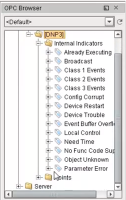
Each response received from a connected outstation will contain an Internal Indication (IIN) bit field. This field indicates certain states or error conditions in the outstation. IINs are mapped to read-only points, indicating the following:
- Broadcast message received (Broadcast)
- Additional Class 1, 2, or 3 event data is available (Class 1 Events, Class 2 Events, Class 3 Events)
- Time synchronization required in the outstation (Need Time)
- Some output points are in local mode (Local Control)
- An abnormal condition exists (Device Trouble)
- The outstation device has restarted (Device Restart)
- Function code not implemented (No Func Code Support)
- Object Unknown (Object Unknown)
- Request parameter error (Parameter Error)
- Outstation event buffer overflow (Event Buffer Overflow)
- An operation is already executing (Already Executing)
- Configuration corrupt (Config Corrupt)
Terminology
- Unsolicited response: An Application Layer message from an outstation to a master for which no explicit request was received. The request is implied by the act of a master enabling unsolicited reporting of various points within an outstation.
- Integrity poll: Requests all event data, followed by the static data of all points assigned to one of the four classes (static Class 0 or event Class 1, 2, or 3).
- DNP3TIME: Universal Coordinated Time (UTC) time expressed as the number of milliseconds since the start of January 1, 1970. The effective date for using the UTC time base is January 1, 2008. Prior to this, DNP3 did not require a specific time reference.
Browsing DNP3 Points
When the driver (master) connects to a device (outstation), an integrity poll is performed. Any DNP3 objects returned in the response that fall under the Point Type categories listed in the table on the right are mapped to the OPC server with the appropriate index. (For example, g40v1i2 corresponds to an AnalogOutput point, variation 1, index 2.)
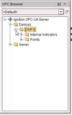
To see the points mapped, you can go to the Designer, open the OPC Browser, and drill down to the DNP3 connection node.
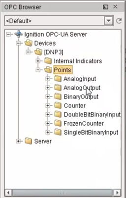
Point Types
| Type Name | Group | Supported Variations |
|---|---|---|
| SingleBitBinaryInput | 1 | |
| DoubleBitBinaryInput | 3 | |
| BinaryOutput | 10 | |
| Counter | 20 | |
| FrozenCounter | 21 | |
| AnalogInput | 30 | |
| FrozenAnalogInput | 31 | |
| AnalogOutput | 40 | |
| OctetString | 110 | 0 - 255 |
Aliased Points
Aliased points allow the user to assign meaningful names and descriptions to DNP3 points. They are also useful for addressing any points that were not returned by the initial integrity-poll on connection.
| Point Attribute | Description |
|---|---|
| Point Address | The group, variation, and index that fully describe a point. A full address consists of all three parts:
g30v1i20 |
| Path | A “/” separated folder hierarchy in which to create the aliased point. Example: Facility1/Voltage |
| Description | A user-defined description of the point mapping. |