Device Diagnostic Tags to Show PLC Status
To use a diagnostic tag to show the PLC status
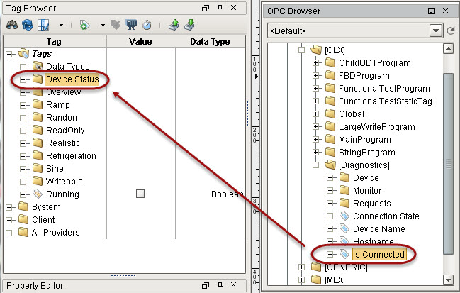
Let's use the Is Connected tag to show the status of each PLC.
-
Create a folder in Tag Browser to contain the status bits by right-clicking on the Tags folder and selecting New Folder.
-
Name the folder Device Status and click OK.
-
Drag in the Is Connected tag from the CLX device into the Device Status folder.
-
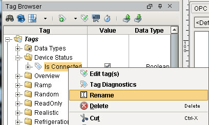
Right-click on the Is Connected tag and rename it to CLX.
-
Repeat steps 3 and 4 for all device connections you have in Ignition. If you have 5 devices, you will have 5 tags.
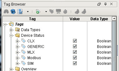
Now that we have a tag for each of the 5 PLCs, let's display the status of each PLC. For example in our Header window, we can make a PLC graphic and color it based on the state: 0 = red, 1 = green.
-
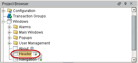
In the Project Browser, double-click the Header window to open it.
We will add a PLC graphic from Symbol Factory to the Header.
-
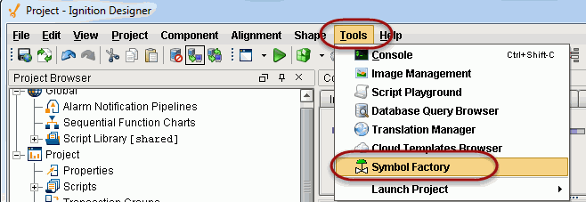
From the Tools menu, select Symbol Factory.
-
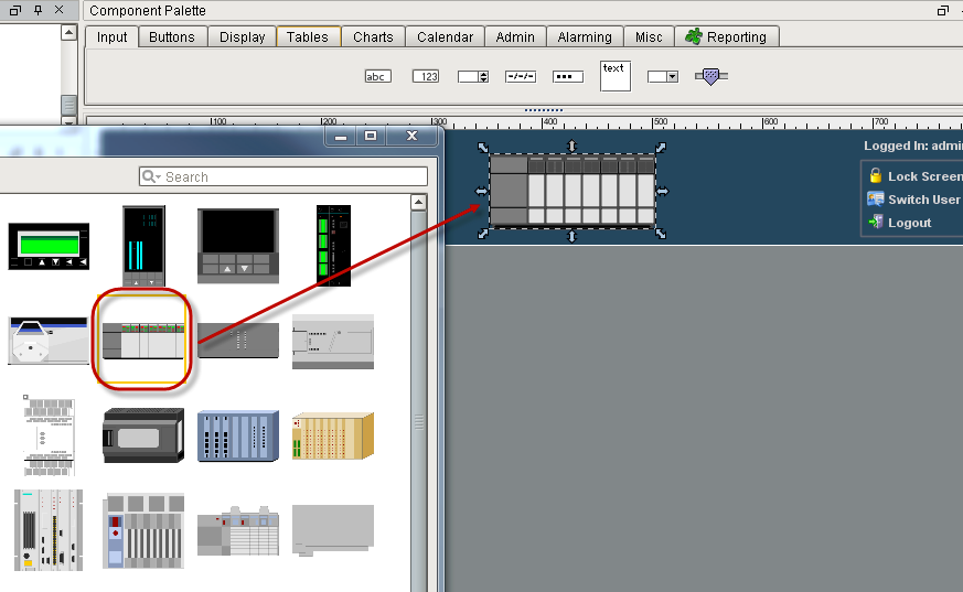
From the Symbol Factory window, select Controllers in the list.
-
Drag any device on the window to create the component (the PLC graphic).
Symbol Factory components are made of several subcomponets or paths that make up a vector-based graphic. If you expand the component in the Project Browser, you can see all the paths. You can also double-click on the component in the design space to select the individual subcomponets. Fill color can be applied to each of these sub-components (or paths) dynamically through property binding. But there are two problems with applying color to the entire component. One is that you would have to change the fill color of each subcomponent dynamically through property binding which can take some time. Two, you will notice that you cannot bind the fill paint to a gradient color. To resolve these two problems we use a special method as described here to apply a tint to the entire component.
-
To apply tint to the entire component, duplicate the component by selecting it and then select Edit > Duplicate from menu or press Ctrl-D.
-
Select the duplicated component, which is above the original component.
-
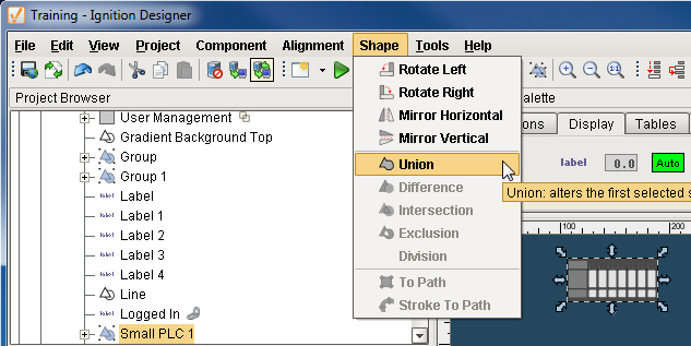
Select Shape > Union from menu or click the Union button in the toolbar. This flattens the duplicated shape into a single shape.
-
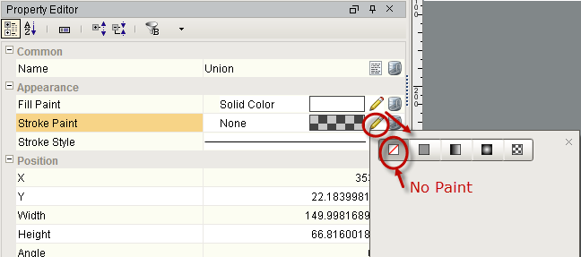
Remove the outline of the shape by clicking on the pencil icon of the Stroke Paint property and selecting No Paint.
-
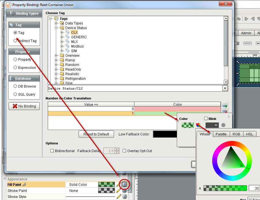
Bind the Fill Paint property to the CLX status tag. Notice when binding a color property to a tag, you get to choose a color for each state of the tag in Number-to-Color Translation. You can also make the colors to blink between two different colors.
-
In Number-to-Color Translation, set value 0 = red, value 1 = green, and alpha channel of each color to 30 (make sure each color is semitransparent so you can see the actual symbol behind it).
-
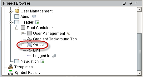
Group the two components together into one by selecting both components from the Project Browser and clicking the Component > Group or Combine icon in the toolbar. Now they are one component.
-
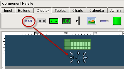
To name the device, drag in the label component from the Display tab into the window under the graphic.
-
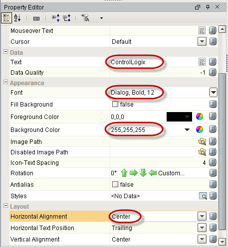
Set the label properties as follows:
- Text: ControlLogix
- Font: Dialog, Bold, 12
- Foreground Color: 255,255,255
- Horizontal Alignment: Center
-
Repeat for each PLC.
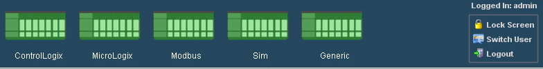
You can now see the status of each PLC based on the colors they display (0=red, 1=green).