DNP3
DNP3 is a communication protocol commonly used in water and electric utilities. It connects a central master station to multiple remote devices, known as outstations, creating a distributed network without overwhelming the communication infrastructure. This page covers connection details and general protocol requirements for using DNP3.
Compared to Modbus, DNP3 is a newer and more robust protocol. It supports a wider range of features but is also more complex. Always consult your device documentation to confirm whether DNP3 is supported.
The DNP3 drivers do not support DNP3 Secure Authentication.
DNP3 Drivers
Ignition provides two DNP3 drivers:
The DNP3 driver is installed by default on new Ignition installations. The DNP3 Driver (Legacy) remains available as an optional module but no longer receives updates or ongoing support.
Scripting Functions
The DNP3 Driver and DNP3 Driver (Legacy) use the following syntax for their respective scripting functions to avoid namespace conflicts:
- The DNP3 Driver uses the system.dnp scripting namespace.
- The DNP3 Driver (Legacy) uses the system.dnp3 namespace.
See the scripting functions appendix for details.
Supported Operating Systems
Both DNP3 drivers are supported on:
- Windows x64
- Linux x64
- Linux arm32
- Linux arm64
The native libraries for both drivers are not currently supported on macOS.
Terminology
| Term | Definition |
|---|---|
| Unsolicited Response | A message sent from the outstation to the master without a direct request. This behavior is enabled when the master allows unsolicited reporting of points. |
| Integrity Poll | A request from the master that gathers all current event data (Classes 1–3), followed by the static data (Class 0) for each configured point. |
| DNP3TIME | A timestamp format in UTC, measured as the number of milliseconds elapsed since January 1, 1970. As of 2008, this format is the required time base for all DNP3 timestamps. |
Upgrading from DNP3 Driver (Legacy)
To migrate from the DNP3 Driver (Legacy):
- Delete or rename the existing Legacy device.
- Create a new DNP3 Driver device and in the name field, use the old DNP3 Driver (Legacy) name.
- Update any tag references as needed.
Review the new driver’s settings carefully, since its configuration and polling model differ from the Legacy driver.
Addressing and Data Acquisition
Ignition's DNP3 drivers use either event-based polling, unsolicited messaging, or group/variation/index (GVI) addressing for explicit data reads from the PLC. See the DNP3 Driver and DNP3 Driver (Legacy) pages for the specific types of data acquisition each driver uses.
Addressing and Browsing DNP3 Points Examples
These sections assume you have already set up a DNP3 connection to a supported device. For instructions on connecting to a device using DNP3, see the DNP3 Driver page, or the DNP3 Legacy Driver page, depending on the DNP3 driver you are using.
Browsing Points With DNP3
This example uses the DNP3 driver to browse for points within the Tag Browser's Connected Devices window.
-
In your Tag Browser, click on the Add
 icon, then click on Browse Devices...
  . The Connected Devices popup window will open.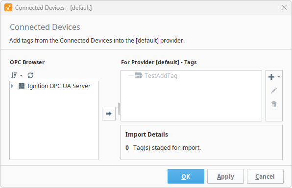
-
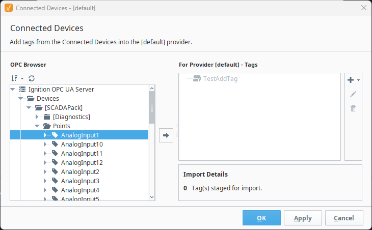
Navigate to the tag you want to import. In this example, since we want AnalogInput1 within our connected device, we'll go through Ignition OPC UA Server > Devices > [SCADAPack] > Points > AnalogInput1.
-
Select the tag or folder to import and add it to your Tag Provider by clicking on the Add
 icon. This will stage the tag for when you are ready to import, in case you want to add any other tags or folders.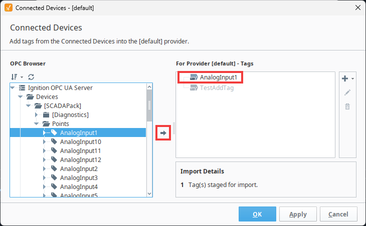
-
Once you have added the tags and folders you want, click OK to add them to your Tag Browser.
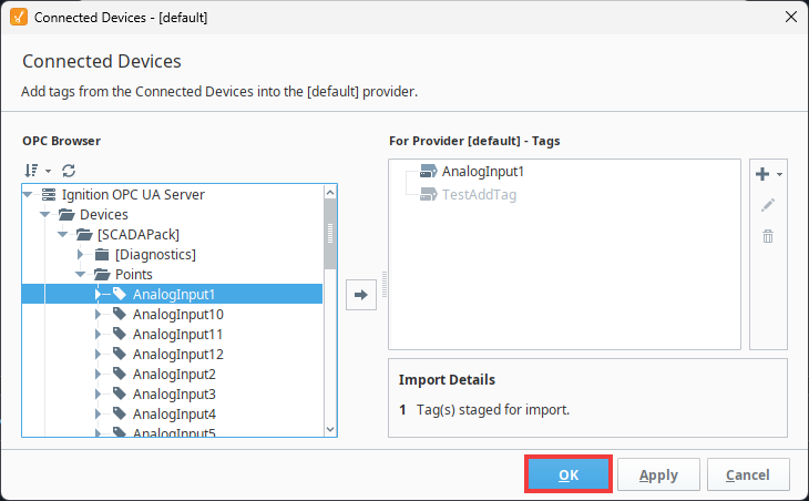
Your tags and folders are now available to use in Ignition.
Browsing Points With Legacy DNP3 (Aliased Points)
This example uses the legacy DNP3 driver to add a single aliased point. If you want to add multiple aliased points at the same time, see Importing Global Variables - CSV File.
The DNP3 driver does not support aliased points. This feature is available on the DNP3 Driver (Legacy) only.
-
Navigate to the Gateway Webpage > Connections > Devices > Connections.
-
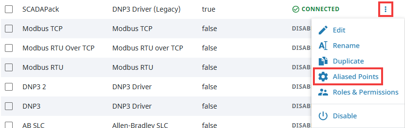
Click the three dots menu of the legacy DNP3 connection you want to add a data point for, then click Aliased Points.
-
The Program panel for your legacy DNP3 connection will open. Click on the Add + button on the top right of the panel. This will add a new entry to the table where you can specify an aliased point.

-
Enter the information for the aliased point you want to map, then click Save Changes on the bottom right.

Your aliased point is now exposed to Ignition. You can now browse for this aliased point in the Tag Browser's Connected Devices window and add it to Ignition by following the Browsing Points with DNP3 Example above.
Importing Global Variables - CSV File
This example describes how to import CSV configuration files to define aliased points for the DNP3 legacy driver.
- On the Gateway, go to Connections > Devices > Connections.
- Locate your DNP3 device, click the three dots menu, and choose Aliased Points.
- Click Import Configuration File and upload your CSV.
- Review the imported entries, then click Save Changes.
Internal Indicators
Each response from an outstation includes an Internal Indication (IIN) bit field. This field reports various states or error conditions within the device. These IIN bits are exposed as read-only points. Refer to the table below for descriptions of what the exposed IIN bits indicate.
| DNP3 IIN Bit | Indicator | Description |
|---|---|---|
| IIN1.0 | Broadcast Message Received | A broadcast message was received. |
| IIN1.1 | Class 1 Events | Additional Class 1 event data is available. |
| IIN1.2 | Class 2 Events | Additional Class 2 event data is available. |
| IIN1.3 | Class 3 Events | Additional Class 3 event data is available. |
| IIN1.4 | Need Time (Time Synchronization Requred) | The outstation requires time synchronization. |
| IIN1.5 | Local Control (Digital Outputs Paused) | One or more outputs are in local (manual) control mode. |
| IIN1.6 | Device Trouble | An abnormal condition exists within the device. |
| IIN1.7 | Device Restart | The outstation has restarted. |
| IIN2.0 | No Func Code Support | The requested function code is not implemented. |
| IIN2.1 | Object Unknown/Unknown Type ID | The requested object is unknown or unsupported. |
| IIN2.2 | Parameter Error | There was an error with one or more request parameters. |
| IIN2.3 | Event Buffer Overflow | The outstation’s event buffer has overflowed. |
| IIN2.4 | Already Executing | A previously requested operation is still executing. |
| IIN2.5 | Configuration Corrupt | The outstation's configuration is corrupted. |
| IIN2.6 | Reserved | This bit is reserved to ensure future compatibility. |
| IIN2.7 | Reserved | This bit is reserved to ensure future compatibility. |
Buffered Events
Buffered events allow missed events to be preserved and replayed after a disconnect. This feature can be enabled by setting the Queue Size property on the corresponding Tag Group to a value greater than 1.
The Queue Size determines how many events the driver will buffer per tag. The driver retains only the most recent events, dropping older ones when the buffer is full. For example, if the Queue Size is set to 20 and 30 value changes occur while the device is disconnected, the 10 oldest events will be dropped.
When the connection is restored, the driver plays back buffered events in order from oldest to newest. This updates the corresponding Ignition tag for each event, which can trigger value changes in systems such as:
- Alarms and Alarm Journals
- Tag History (in On Change mode)
- Tag Event Scripts
Once playback completes, the tag resumes showing live values.
This Buffered Events feature can only be used by devices that support Sequence of Events (SoE). The SoE data type may differ from the standard data type returned by subscriptions. This may be due to a configuration on the Default Variation property in the device.