Allen-Bradley Ethernet
Connecting to Allen-Bradley Devices
Ignition provides several drivers for Allen-Bradley devices. These drivers connect through the Gateway to devices that support Ethernet communication or devices with Ethernet modules like ENBT or EN2T. The following device drivers are available in the Allen-Bradley Ethernet module:
- CompactLogix (Legacy): Supports legacy firmware versions v20.18 and prior.
- ControlLogix (Legacy): Supports legacy firmware versions v20.18 and prior.
- Logix: Supports ControlLogix and CompactLogix devices with firmware v20.19 and later.
- Micro800: Supports Micro800 models including 820, 850, and 870.
- MicroLogix: Supports MicroLogix models including 1100 and 1400 series.
- PLC5: Supports direct communication with Allen-Bradley PLC5 controllers.
- SLC: Supports the 5/05 series using Ethernet.
These drivers only support firmware versions 16 and above. Earlier versions may work, but are not officially supported. For unsupported versions, consider using a third party OPC server.
Reading Add On Instructions (AOI) within Add On Instructions is not supported by Allen-Bradley. Tags with this architecture cannot be browsed in RSLogix and RSLinx.
Alias tag types can be used to read and write to members inside of AOIs that reside within another AOI.
Direct connections to RSLinx Emulate 5000 are not supported and may result in communication issues.
Verifying Device Connectivity
Device connections can be verified from the Gateway Webpage under Connections > Devices > Connections. Check the Status column to confirm that the device shows Connected.
Allen-Bradley Connection Paths
All Allen-Bradley drivers include a Connection Path setting. This setting is required when you're connecting to a processor through a bridge device or an external Ethernet module, such as an ENBT or EN2T. For example, if you're communicating with a ControlLogix or CompactLogix processor via a ControlLogix Gateway, you'll need to define a connection path.
The connection path tells the driver how to navigate through backplanes, modules, and network links to reach the destination processor. Because hardware configurations vary widely, the path is unique to your setup. However, most connection paths follow a consistent pattern. For detailed examples and templates, refer to the individual driver documentation.
How to Build a Connection Path
Building a connection path involves identifying each segment between Ignition and the processor, then expressing those steps in the expected format. The path is always defined in pairs: an action (such as exiting a port) followed by a destination (such as an IP address or slot).
-
Begin the path with a 1, which tells the driver to move from the current module (such as an Ethernet card) into the chassis backplane, where it can access other modules by slot.
-
Enter the slot number of the module you want to route through.
-
Specify the exit port or channel on that module.
-
Provide the address of the next module in the path—this could be an IP address, ControlNet address, or DH+ station number, depending on the network type.
Repeat this pattern as needed until you reach the processor.
Since each step consists of two entries, all valid connection paths must contain an even number of values. If your path ends in an odd number, a step is likely missing.
Module Entry and Exit Codes
Each movement in the path consists of two entries: one for exiting a module and one for entering the next. This means all valid paths contain an even number of entries. If your path ends with an odd number of entries, a step is missing.
By following the path through your networked modules, you can configure communication from Ignition to any accessible Allen-Bradley processor.
Use the following codes based on the module type:
ENET, ENBT, and EN2T:
Exiting:
    1 = Backplane
    2 = Ethernet Port
Entering:
    IP Address

CNB:
Exiting:
    1 = Backplane
    2 = ControlNet Port
Entering:
    ControlNet Address

DHRIO:
Exiting:
    1 = Backplane
    2 = DH+ Channel A
    3 = DH+ Channel B
Entering:
    DH+ Station Number (octal 0–77)
Allen-Bradley Addressing
Ignition's Allen-Bradley drivers all use tag-based (symbolic) addressing, meaning Ignition will automatically browse the connected device for data points that can be added to the Tag Browser. Additionally, the Micro800 driver allows users to either create entries for individual data points, or import configuration files.
Addressing Example
This example uses the Logix driver to browse for data points within the Tag Browser's Connected Devices window and assumes you have already set up a connection to a ControlLogix PLC. For instructions on connecting to a device using the Logix driver, see the Connect to a Logix Device section.
-
In your Tag Browser, click on the Add
 icon, then click on Browse Devices...
  . The Connected Devices popup window will open.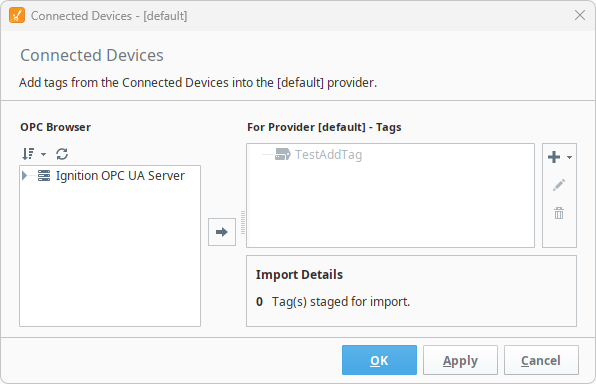
-
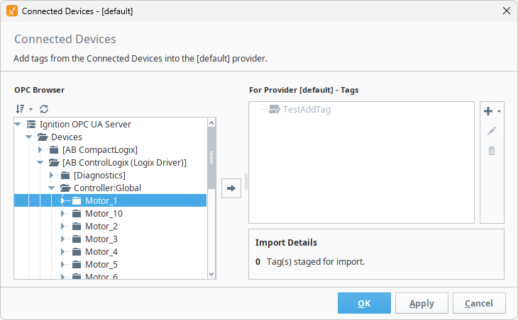
Navigate to the tag you want to import. In this example, since we want Motor_1 within our connected device, we'll go through Ignition OPC UA Server > Devices > [AB ControlLogix (Logix Driver)] > Controller:Global > Motor_1.
-
Select the tag or folder to import and add it to your Tag Provider by clicking on the Add
 icon. This will stage the tag for when you are ready to import, in case you want to add any other tags or folders.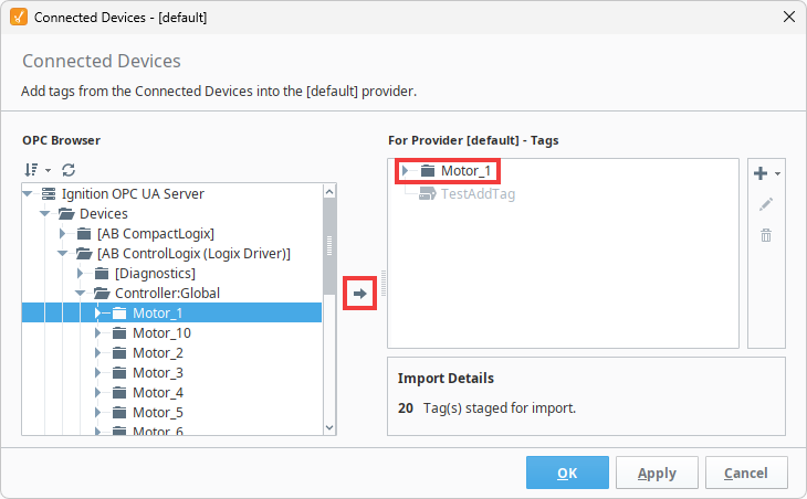
-
Once you have added the tags and folders you want, click OK to add them to your Tag Browser.
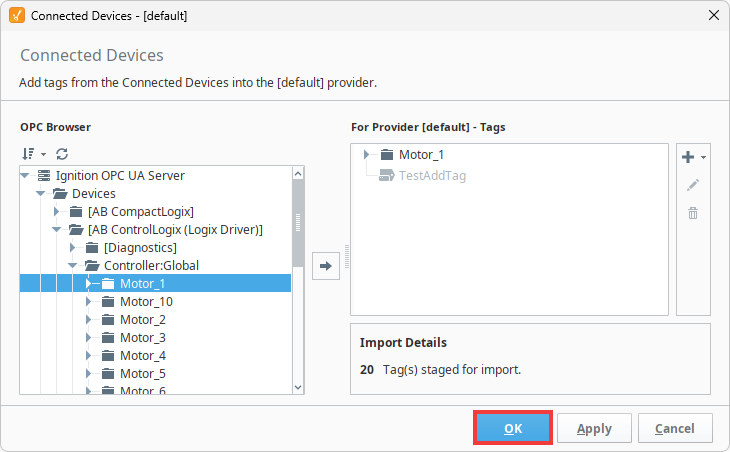
Your tags and folders are now available to use in Ignition.
Configuring Data Points
You can expose individual data points to your device connection program so that Ignition knows where to browse for them. Alternatively, if you have a CSV or ZIP file, you can import those instructions to avoid needing to configure data points manually. Currently, only the Allen-Bradley Micro800 driver supports manually adding data points.
Besides importing configuration files, there are various other options you can select, all of which are outlined by the table below:
| Button | Description |
|---|---|
| Import Configuration File | Allows users to import a CSV or ZIP file to add many data points at once. |
| Reset | Resets the program to its default state before any changes were saved. |
| Export | Allows users to export the configuration file as a CSV. |
| Remove All | Removes all entries from the program. |
| Add + | Allows users to manually add individual data points. |
When adding individual data points or importing configuration files, it is helpful to know what fields Ignition is expecting. These fields are detailed by the table below:
| Property | Description |
|---|---|
| Browse Name | The path to the data point on the PLC. |
| Data Type | The data point's data type. See the Micro800's Data Types section for a list of supported data types. |
| Dimension | The structure of the PLC's data points, defined by arrays. This lets you use arrays in different dimensions, such as vectors and matricies. For example, [0..9] is a one dimensional array with 10 elements, while [0..4,0..5] is a two dimensional array with 30 elements (five rows by six columns). |
| String Size | The maximum size of the string. Applicable only for STRING data types. |
| Read Write | The permission level Ignition has to these data points. Options include
|
Configuring Data Points Example
This example demonstrates how to add a single data point to your Micro800 device connection and assumes you have already set up a connection to a Micro800 PLC. For instructions on connecting to a device using the Micro800 driver, see the Connect to a Micro800 Device section. If you want to add multiple data points at the same time, see the Micro800 driver page for examples on importing and using CSV and ZIP files.
-
Navigate to Gateway Webpage > Connections > Devices > Connections.
-
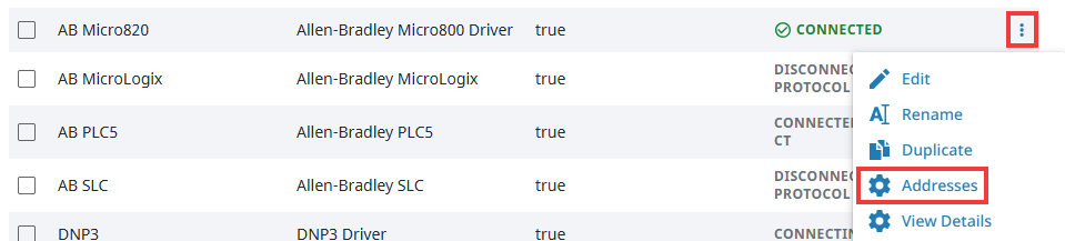
Click the three dots menu of the Micro800 device you want to add a data point for, then click Addresses.
-
The Program panel for your Micro800 device will open. Click on the Add + button on the top right of the panel. This will add a new entry to the table where you can specify a data point.

-
Enter the information for the data point you want to expose, then click Save Changes on the bottom right.
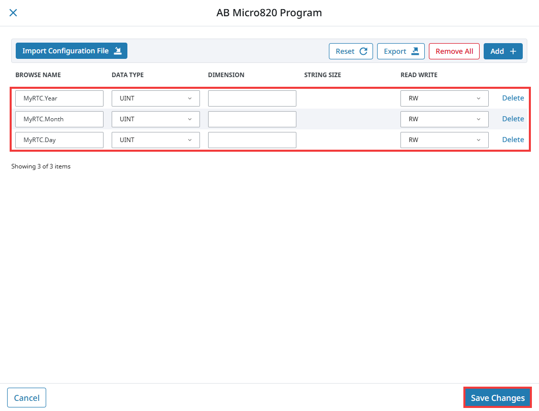
Your data point is exposed to Ignition. You can now browse for this data point in the Tag Browser's Connected Devices window and add it to Ignition by following the addressing example above.